
Service Manual
Page 1
SY298XLHP500/ MICRO COMPONENT SYSTEM MODEL XL-HP500 XL-HP500 Micro Component System consisting of XL-HP500 (main unit) and CP-HP500 (speaker system). • In the interests of user-safety the set should be restored to its original condition and only parts identical to those specified be ... OF CD CIRCUIT ...34 TROUBLESHOOTING ...35 FUNCTION TABLE OF IC ...39 FL DISPLAY ...46 REPLACEMENT PARTS LIST/EXPLODED VIEW PACKING OF THE SET (FOR U.S.A. ONLY) SHARP CORPORATION This document has been published to change without notice.
SY298XLHP500/ MICRO COMPONENT SYSTEM MODEL XL-HP500 XL-HP500 Micro Component System consisting of XL-HP500 (main unit) and CP-HP500 (speaker system). • In the interests of user-safety the set should be restored to its original condition and only parts identical to those specified be ... OF CD CIRCUIT ...34 TROUBLESHOOTING ...35 FUNCTION TABLE OF IC ...39 FL DISPLAY ...46 REPLACEMENT PARTS LIST/EXPLODED VIEW PACKING OF THE SET (FOR U.S.A. ONLY) SHARP CORPORATION This document has been published to change without notice.
Service Manual
Page 2
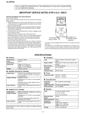
...power Rated input power Impedance Dimensions Weight 2-way type speaker system 2" (5 cm) Tweeter 5-1/8" (13 cm) Woofer 100 W 50 W 6 ohms Width: 6-1/2" (165 mm) Height: 10-1/4" (260 mm) Depth: 9-1/2" (241 mm) 5.5 lbs. (2.5 kg)/each - 2 - XL-HP500 FOR A COMPLETE DESCRIPTION OF THE OPERATION OF THIS ...(recording/playback) 0.3 % (WRMS) s Amplifier (For Canada) Output power Output terminals Input terminals RMS: 100 W (50 W + 50 W) (10 % T.H.D.) Speakers: 6 ohms Headphones: 16 - 50 ohms (recommended: 32 ohms) Subwoofer pre-output (audio signal): 200 mV/10 k ohms at 70 Hz Video/Auxiliary (audio ...
...power Rated input power Impedance Dimensions Weight 2-way type speaker system 2" (5 cm) Tweeter 5-1/8" (13 cm) Woofer 100 W 50 W 6 ohms Width: 6-1/2" (165 mm) Height: 10-1/4" (260 mm) Depth: 9-1/2" (241 mm) 5.5 lbs. (2.5 kg)/each - 2 - XL-HP500 FOR A COMPLETE DESCRIPTION OF THE OPERATION OF THIS ...(recording/playback) 0.3 % (WRMS) s Amplifier (For Canada) Output power Output terminals Input terminals RMS: 100 W (50 W + 50 W) (10 % T.H.D.) Speakers: 6 ohms Headphones: 16 - 50 ohms (recommended: 32 ohms) Subwoofer pre-output (audio signal): 200 mV/10 k ohms at 70 Hz Video/Auxiliary (audio ...
Service Manual
Page 3
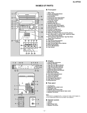
... 4. FM Stereo Mode Indicator 7. Memory Indicator 9. Timer Play Indicator 12. Woofer 3. Disc Trays 1 2. Video/Auxiliary Button 23. Extra Bass Indicator 10. Speaker Terminals Note: This product is equipped with a cooling fan inside, which begins to run at a specified volume level for better heat radiation. Clock Button 2 ... 25 26 1 2 34 5 12 13 1 2 3 1 2 67 8 9 10 11 14 15 4 5 6 3 4 s Display 1. Memory/Set Button 25. FM/AM Loop Antenna Jack 5. s Speaker system 1. Speaker Terminals - 3 - Subwoofer Pre-output Jack 3. NAMES OF PARTS XL-HP500 s Front panel 1.
... 4. FM Stereo Mode Indicator 7. Memory Indicator 9. Timer Play Indicator 12. Woofer 3. Disc Trays 1 2. Video/Auxiliary Button 23. Extra Bass Indicator 10. Speaker Terminals Note: This product is equipped with a cooling fan inside, which begins to run at a specified volume level for better heat radiation. Clock Button 2 ... 25 26 1 2 34 5 12 13 1 2 3 1 2 67 8 9 10 11 14 15 4 5 6 3 4 s Display 1. Memory/Set Button 25. FM/AM Loop Antenna Jack 5. s Speaker system 1. Speaker Terminals - 3 - Subwoofer Pre-output Jack 3. NAMES OF PARTS XL-HP500 s Front panel 1.
Service Manual
Page 9
... 0.1 V FM RF 98.00 MHz 98.00 MHz L312 *2 (10-30 dB) *1. Input: Antenna Output: TP301 MAIN PWB-A1 TRAY error. XL-HP500 ADJUSTMENT MECHANISM SECTION • Tape Speed • Driving Force Check Test Tape Torque Meter Specified Value Play: TW-2111 • Torque Check Over 80.... * 'CHECKING' If Error is 20* moving . Therefore, different PWBs and pickups can be combined freely. Input: Antenna Output: Speaker terminal • FM IF Signal generator: 10.7 MHz, FM modulated Test Stage Frequency Frequency Display Setting/ Instrument Adjusting Connection Point IF ...
... 0.1 V FM RF 98.00 MHz 98.00 MHz L312 *2 (10-30 dB) *1. Input: Antenna Output: TP301 MAIN PWB-A1 TRAY error. XL-HP500 ADJUSTMENT MECHANISM SECTION • Tape Speed • Driving Force Check Test Tape Torque Meter Specified Value Play: TW-2111 • Torque Check Over 80.... * 'CHECKING' If Error is 20* moving . Therefore, different PWBs and pickups can be combined freely. Input: Antenna Output: Speaker terminal • FM IF Signal generator: 10.7 MHz, FM modulated Test Stage Frequency Frequency Display Setting/ Instrument Adjusting Connection Point IF ...
Service Manual
Page 11
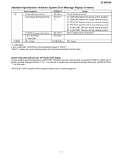
...23: Invalid TRAY SW value during initialize process. XL-HP500 Standard Specification of 'ER-CD**' . 'ER-CD**' display will only be check by pressing 'POWER', 'VIDEO' and 'XBASS' key twice. Speaker abnormal detection and +B PROTECTION display In case speaker abnormal detection or +B PROTECTION had occurred, it ...times. DISPLAY 'ER-CD01' 'ER-CD**' (*) CD DSP Communication Error Focus Not Match/ IL Time Over. S is referring to speaker abnormal detection and B is referring to +B PROTECTION. ** is in hex valve. +B PROTECTION is detected, 'CHECKING' will show "S** B**". CD Changer Mechanism...
...23: Invalid TRAY SW value during initialize process. XL-HP500 Standard Specification of 'ER-CD**' . 'ER-CD**' display will only be check by pressing 'POWER', 'VIDEO' and 'XBASS' key twice. Speaker abnormal detection and +B PROTECTION display In case speaker abnormal detection or +B PROTECTION had occurred, it ...times. DISPLAY 'ER-CD01' 'ER-CD**' (*) CD DSP Communication Error Focus Not Match/ IL Time Over. S is referring to speaker abnormal detection and B is referring to +B PROTECTION. ** is in hex valve. +B PROTECTION is detected, 'CHECKING' will show "S** B**". CD Changer Mechanism...
Service Manual
Page 15
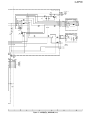
Q702 +B10 RESET FAN MOTOR DRIVER Q906 +B7 M971(212-3) M FAN MOTOR IC901 STK402-071 POWER AMP. XL-HP500 Q603 Q604 SYSTEM MUTE C/PLAY BIAS FL701 FL DISPLAY 1 5 ~ 12 13 15 ~ 19 29 ~ 34 35 ~41 14 45 +B9 Q701 +B10 TO CD SECTION ... XL700 4.19403 MHz TO CD SECTION CNP5 SP DET. L1 R 15 13 7 L-OUT 10 R-OUT 89 Q901~ Q904 SP RELAY ON-OFF Q905 RL914 SO901 SPEAKER TERMINAL +B3 JK951 HEADPHONES JK953 SUB WOOFER -B2 IC851 KIA7812AP F802 CONSTANT 4A 125V VOLTAGE +B2 REGULATOR D802 F801 4A 125V M_+12.6V +B3...
Q702 +B10 RESET FAN MOTOR DRIVER Q906 +B7 M971(212-3) M FAN MOTOR IC901 STK402-071 POWER AMP. XL-HP500 Q603 Q604 SYSTEM MUTE C/PLAY BIAS FL701 FL DISPLAY 1 5 ~ 12 13 15 ~ 19 29 ~ 34 35 ~41 14 45 +B9 Q701 +B10 TO CD SECTION ... XL700 4.19403 MHz TO CD SECTION CNP5 SP DET. L1 R 15 13 7 L-OUT 10 R-OUT 89 Q901~ Q904 SP RELAY ON-OFF Q905 RL914 SO901 SPEAKER TERMINAL +B3 JK951 HEADPHONES JK953 SUB WOOFER -B2 IC851 KIA7812AP F802 CONSTANT 4A 125V VOLTAGE +B2 REGULATOR D802 F801 4A 125V M_+12.6V +B3...
Service Manual
Page 17
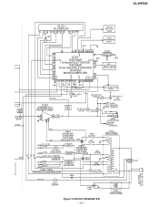
...12 Figure 17 SCHEMATIC DIAGRAM (2/11) - 17 - A CNP801 TO POWER PWB 801 1 2 3 4 5 6 6V 7 +B 8 LUG902(229) CHASSIS GND CNS801 1 2 3 4 5 6 7 XL-HP500 Q906 KTC3203 Y WT902 + D912 DS1SS133 MAIN PWB-A1(1/3) C930 47/50 2 2 1 1 M971 FAN MOTOR (212-3) M R949 1K (1/2W) CNP971 CNS971 R947 15K C931 10/50 +B ...FW903 JACK PWB-A4 1 R965 8.2K (1/2W) 2 R966 3 8.2K (1/2W) JK953 SUB WOOFER WT904 R967 680 (1/2W) C960 3.3/25 + L-CH + R-CH SO901 SPEAKERS 6 OHMS MIN - +B L R C927 0.22 (ML) R941 4.7 (1/2W) C929 0.22 (ML) RL914 R945 2.2K R944 2.2K R_OUT L_OUT D911 DS1SS133 0.2V Q905 ...
...12 Figure 17 SCHEMATIC DIAGRAM (2/11) - 17 - A CNP801 TO POWER PWB 801 1 2 3 4 5 6 6V 7 +B 8 LUG902(229) CHASSIS GND CNS801 1 2 3 4 5 6 7 XL-HP500 Q906 KTC3203 Y WT902 + D912 DS1SS133 MAIN PWB-A1(1/3) C930 47/50 2 2 1 1 M971 FAN MOTOR (212-3) M R949 1K (1/2W) CNP971 CNS971 R947 15K C931 10/50 +B ...FW903 JACK PWB-A4 1 R965 8.2K (1/2W) 2 R966 3 8.2K (1/2W) JK953 SUB WOOFER WT904 R967 680 (1/2W) C960 3.3/25 + L-CH + R-CH SO901 SPEAKERS 6 OHMS MIN - +B L R C927 0.22 (ML) R941 4.7 (1/2W) C929 0.22 (ML) RL914 R945 2.2K R944 2.2K R_OUT L_OUT D911 DS1SS133 0.2V Q905 ...
Service Manual
Page 44
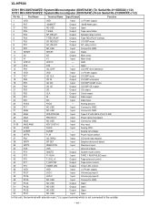
...P20 25 AVSS CD DI CD DO CD CE CE CLK DI DO AVSS Output Input Output Output Output Output Input - Speaker abnormal detect. XL-HP500 IC701 RH-iX0574AWZZ: System Microcomputer (IX0574AW) (To Serial No.211XXXXX) (1/2) IC701 RH-iX0578AWZZ: System Microcomputer (IX0578AW) (From ...Serial No.212XXXXX) (1/2) Pin No. Speaker relay control. Data output. Key input. Remocon input. CD DSP CODE Q out. Volume jog input 2. Power ...
...P20 25 AVSS CD DI CD DO CD CE CE CLK DI DO AVSS Output Input Output Output Output Output Input - Speaker abnormal detect. XL-HP500 IC701 RH-iX0574AWZZ: System Microcomputer (IX0574AW) (To Serial No.211XXXXX) (1/2) IC701 RH-iX0578AWZZ: System Microcomputer (IX0578AW) (From ...Serial No.212XXXXX) (1/2) Pin No. Speaker relay control. Data output. Key input. Remocon input. CD DSP CODE Q out. Volume jog input 2. Power ...
Service Manual
Page 47
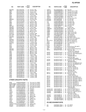
... filled promptly and correctly, please furnish the following information. 1. "HOW TO ORDER REPLACEMENT PARTS" To have your nearest SHARP Parts Distributor to replace parts with " " are no indications for maintaining the safety of the set . For U.S.A. ...SHARP Parts Distributor, Please call Toll-Free; 1-800-BE-SHARP MARK: SPARE PARTS-DELIVERY SECTION Explanation of XL-HP500 (main unit) and CP-HP500 (speaker system). NOTE: Parts marked with specified ones for the electrolytic capacitors, error is ±20%. PARTS GUIDE XL-HP500 MICRO COMPONENT SYSTEM MODEL XL-HP500 XL-HP500...
... filled promptly and correctly, please furnish the following information. 1. "HOW TO ORDER REPLACEMENT PARTS" To have your nearest SHARP Parts Distributor to replace parts with " " are no indications for maintaining the safety of the set . For U.S.A. ...SHARP Parts Distributor, Please call Toll-Free; 1-800-BE-SHARP MARK: SPARE PARTS-DELIVERY SECTION Explanation of XL-HP500 (main unit) and CP-HP500 (speaker system). NOTE: Parts marked with specified ones for the electrolytic capacitors, error is ±20%. PARTS GUIDE XL-HP500 MICRO COMPONENT SYSTEM MODEL XL-HP500 XL-HP500...
Service Manual
Page 51
... AB Plug,5Pin AC Socket,13Pin AB Plug,6Pin AC Plug,8Pin AC Plug,3Pin AD Socket,16Pin AB Plug,5Pin AC Plug,7Pin NO. XL-HP500 NO. PARTS CODE PRICE RANK DESCRIPTION CNP971 CNS1A/B CNS2A/B CNS3A/B CNS4 CNS8 CNS702 CNS971 1 F801,802 1 F803,804 FC5 FC6 FC701 FC702 FL701 FW804 FW804A... [Sled] AM Motor,Air Cooling Fan AQ Main Cam Motor Ass'y AQ Tray Motor Ass'y AH Relay AK Relay AH Remote Sensor,GP1UM271 AE Terminal,Speaker AD Switch,Leaf Type [PICKUP IN] AC Switch,Key Type [POWER ON/STAND BY] AC Switch,Key Type [CLOCK] AC Switch,Key Type [TIMER/SLEEP...
... AB Plug,5Pin AC Socket,13Pin AB Plug,6Pin AC Plug,8Pin AC Plug,3Pin AD Socket,16Pin AB Plug,5Pin AC Plug,7Pin NO. XL-HP500 NO. PARTS CODE PRICE RANK DESCRIPTION CNP971 CNS1A/B CNS2A/B CNS3A/B CNS4 CNS8 CNS702 CNS971 1 F801,802 1 F803,804 FC5 FC6 FC701 FC702 FL701 FW804 FW804A... [Sled] AM Motor,Air Cooling Fan AQ Main Cam Motor Ass'y AQ Tray Motor Ass'y AH Relay AK Relay AH Remote Sensor,GP1UM271 AE Terminal,Speaker AD Switch,Leaf Type [PICKUP IN] AC Switch,Key Type [POWER ON/STAND BY] AC Switch,Key Type [CLOCK] AC Switch,Key Type [TIMER/SLEEP...
Service Manual
Page 53
.... PART CODE PRICE RANK DESCRIPTION SPEAKER BOX PARTS 901 901- 1 901- 2 901- 3 901- 4 901- 5 901- 6 902 902- 1 902- 2 902- 3 903 903- 1 903- 2 904 905 906 SP1,2 SP3,4 GBOXS0112AWSA J ---- Net Flame (Not Replacement Item) AD Badge,SHARP AC Label,Specification AA Screw,ø... [For Canada] AG Quick Guide [Except for Canada] AS Remote Control Battery Lid,Remote Control P.W.B. XL-HP500 QCNWN2421AWZZ J PCUSG0138AWZZ J QTANA9010AWZZ J PCOVZ1022AWSA J PDUC-0015AWSA J CPNLS1074AW01 J ---- Speaker Box (Not Replacement Item) AM Network Cord AC Cushion,Foot AG Terminal AL Cover,Duct Pipe Duct ...
.... PART CODE PRICE RANK DESCRIPTION SPEAKER BOX PARTS 901 901- 1 901- 2 901- 3 901- 4 901- 5 901- 6 902 902- 1 902- 2 902- 3 903 903- 1 903- 2 904 905 906 SP1,2 SP3,4 GBOXS0112AWSA J ---- Net Flame (Not Replacement Item) AD Badge,SHARP AC Label,Specification AA Screw,ø... [For Canada] AG Quick Guide [Except for Canada] AS Remote Control Battery Lid,Remote Control P.W.B. XL-HP500 QCNWN2421AWZZ J PCUSG0138AWZZ J QTANA9010AWZZ J PCOVZ1022AWSA J PDUC-0015AWSA J CPNLS1074AW01 J ---- Speaker Box (Not Replacement Item) AM Network Cord AC Cushion,Foot AG Terminal AL Cover,Duct Pipe Duct ...

Service Manual
Page 57
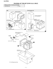
XL-HP500 A TWEETER SP1(L-CH) SP2(R-CH) Capacitor 2.2µ,100V WOOFER B SP3(L-CH) SP4(R-CH) 902 902-3x2 C 902-1 902-2x2 TWEETER SP1(L-CH) SP2(R-CH) RED Capacitor 2.2µ,100V BK RED BK WOOFER SP3(L-CH) SP4(R-CH) 901 901-2 D 902-2x2 902-3x2 E 903-2 903-1 903 SP1,2 F 905x2 SP3,4 906x4 G 901-1 901-5 901-6 904 901-4 901-3x4 H 1 2 3 4 5 6 Figure 10 SPEAKER EXPLODED VIEW - 10 -
XL-HP500 A TWEETER SP1(L-CH) SP2(R-CH) Capacitor 2.2µ,100V WOOFER B SP3(L-CH) SP4(R-CH) 902 902-3x2 C 902-1 902-2x2 TWEETER SP1(L-CH) SP2(R-CH) RED Capacitor 2.2µ,100V BK RED BK WOOFER SP3(L-CH) SP4(R-CH) 901 901-2 D 902-2x2 902-3x2 E 903-2 903-1 903 SP1,2 F 905x2 SP3,4 906x4 G 901-1 901-5 901-6 904 901-4 901-3x4 H 1 2 3 4 5 6 Figure 10 SPEAKER EXPLODED VIEW - 10 -
Service Manual
Page 58
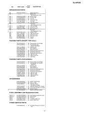
... Sheet,Net Frame SPAKZ1005AWZZ B Polyethylene Bag,Accessories SSAKA0007AWZZ AM Loop Antenna Speaker Cord Remote Control Operation Manual Quick Guide B A Packing Case SPAKC1510AWZZ : Not Replacement Item - 11 - XL-HP500 PACKING OF THE SET (FOR U.S.A. ONLY) Setting position of switches and knobs Tape Mechanism STOP UNIT Polyethylene Bag,Unit SSAKH0094AWZZ Label,Energy Star TLABZ0593AWZZ Packing...
... Sheet,Net Frame SPAKZ1005AWZZ B Polyethylene Bag,Accessories SSAKA0007AWZZ AM Loop Antenna Speaker Cord Remote Control Operation Manual Quick Guide B A Packing Case SPAKC1510AWZZ : Not Replacement Item - 11 - XL-HP500 PACKING OF THE SET (FOR U.S.A. ONLY) Setting position of switches and knobs Tape Mechanism STOP UNIT Polyethylene Bag,Unit SSAKH0094AWZZ Label,Energy Star TLABZ0593AWZZ Packing...

Operation Manual
Page 1
XL-HP500W Micro Component System consisting of XLHP500W (main unit) and CP-HP500W (speaker system). To obtain the best performance from this product, please read this SHARP product. OPERATION MANUAL XLHP500WA_FRONT 1 02.8.7, 9:54 AM It will guide you for purchasing this manual carefully. MICRO COMPONENT SYSTEM MODEL XL-HP500W Thank you in operating your SHARP product.
XL-HP500W Micro Component System consisting of XLHP500W (main unit) and CP-HP500W (speaker system). To obtain the best performance from this product, please read this SHARP product. OPERATION MANUAL XLHP500WA_FRONT 1 02.8.7, 9:54 AM It will guide you for purchasing this manual carefully. MICRO COMPONENT SYSTEM MODEL XL-HP500W Thank you in operating your SHARP product.
Operation Manual
Page 3
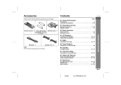
Contents XL-HP500W " General Information Page Precautions 3 Controls and indicators 4 - 6 ENGLISH " Preparation for Use System connections 7 - 10 Remote control 11 " Basic Operation Sound control 12 Setting the ..., 24 " Advanced Features Timer and sleep operation 25 - 27 Enhancing your system 27, 28 " References Troubleshooting chart 29, 30 Maintenance 31 Specifications 31, 32 E-2 02/8/6 XL-HP500W(A)1.fm Accessories Please confirm that the following accessories are included. Remote control 1 "AA" size battery AM loop aerial 1 (UM/SUM-3, R6, HP7 or similar...
Contents XL-HP500W " General Information Page Precautions 3 Controls and indicators 4 - 6 ENGLISH " Preparation for Use System connections 7 - 10 Remote control 11 " Basic Operation Sound control 12 Setting the ..., 24 " Advanced Features Timer and sleep operation 25 - 27 Enhancing your system 27, 28 " References Troubleshooting chart 29, 30 Maintenance 31 Specifications 31, 32 E-2 02/8/6 XL-HP500W(A)1.fm Accessories Please confirm that the following accessories are included. Remote control 1 "AA" size battery AM loop aerial 1 (UM/SUM-3, R6, HP7 or similar...
Operation Manual
Page 4
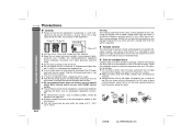
... dangerous and may result in a fire or other factors. NO YES Correct E-3 02/8/6 XL-HP500W(A)1.fm XL-HP500W Precautions ENGLISH " General ! Do not remove the outer cover, as newspapers, tablecloths...mark this unit. Fingerprints, dirt, or water on a firm, level surface free from your local SHARP service facility. ! It is specified. Follow the guidelines below for safety. ! Keep the unit... Do not place anything on to full at moderate levels. Do not turn on speaker efficiency, location, and various other type of compact discs Compact discs are read. Please...
... dangerous and may result in a fire or other factors. NO YES Correct E-3 02/8/6 XL-HP500W(A)1.fm XL-HP500W Precautions ENGLISH " General ! Do not remove the outer cover, as newspapers, tablecloths...mark this unit. Fingerprints, dirt, or water on a firm, level surface free from your local SHARP service facility. ! It is specified. Follow the guidelines below for safety. ! Keep the unit... Do not place anything on to full at moderate levels. Do not turn on speaker efficiency, location, and various other type of compact discs Compact discs are read. Please...
Operation Manual
Page 6
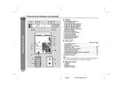
... heat radiation. Bass Reflex Duct 4. Timer Recording Indicator 11. Tape Record Indicator 15. FM 75 Ohms Aerial Terminal 7, 8 6. Span Selector Switch 10 10. Speaker Terminals 02/8/6 XL-HP500W(A)1.fm " Speaker system 1. Disc Number Indicators 2. FM Stereo Receiving Indicator 8. Cooling Fan 3. FM Stereo Mode Indicator 7. CD Repeat Play Indicator 14. Subwoofer Output Socket 28...
... heat radiation. Bass Reflex Duct 4. Timer Recording Indicator 11. Tape Record Indicator 15. FM 75 Ohms Aerial Terminal 7, 8 6. Span Selector Switch 10 10. Speaker Terminals 02/8/6 XL-HP500W(A)1.fm " Speaker system 1. Disc Number Indicators 2. FM Stereo Receiving Indicator 8. Cooling Fan 3. FM Stereo Mode Indicator 7. CD Repeat Play Indicator 14. Subwoofer Output Socket 28...
Operation Manual
Page 8
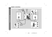
XL-HP500W System connections ENGLISH AM loop aerial FM aerial Preparation for Use Right speaker Left speaker E-7 Red Black Wall socket (See page 9.) Red Black 02/8/6 XL-HP500W(A)1.fm
XL-HP500W System connections ENGLISH AM loop aerial FM aerial Preparation for Use Right speaker Left speaker E-7 Red Black Wall socket (See page 9.) Red Black 02/8/6 XL-HP500W(A)1.fm
Operation Manual
Page 9
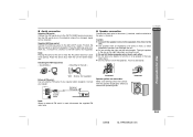
...Use Wall Screws (not supplied) External FM aerial: Use an external FM aerial if you remove the speaker grilles. Consult your dealer. Incorrect E-8 02/8/6 XL-HP500W(A)1.fm Note: Placing the aerial on the speakers. " Use speakers with screws (not supplied). " Do not allow any objects to a stand or a wall with... an impedance of 6 ohms or more, as lower impedance speakers can be received. ENGLISH Caution: " Connect the speaker wires to the speakers first, then to the wall > XL-HP500W ! " Do not stand or sit on the unit or near the AC power lead may...
...Use Wall Screws (not supplied) External FM aerial: Use an external FM aerial if you remove the speaker grilles. Consult your dealer. Incorrect E-8 02/8/6 XL-HP500W(A)1.fm Note: Placing the aerial on the speakers. " Use speakers with screws (not supplied). " Do not allow any objects to a stand or a wall with... an impedance of 6 ohms or more, as lower impedance speakers can be received. ENGLISH Caution: " Connect the speaker wires to the speakers first, then to the wall > XL-HP500W ! " Do not stand or sit on the unit or near the AC power lead may...
Operation Manual
Page 22
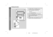
...LEVEL control towards MAX to increase the microphone volume and towards MIN to the MIC socket. ! XL-HP500W Playing karaoke ENGLISH 1 Set the MIC LEVEL control to MIN to protect the speakers from shock noise and to avoid disturbing noises. 2 Connect the microphone to decrease it. Karaoke... E-21 02/8/6 XL-HP500W(A)3.fm Use a microphone with a 3.5 mm (1/8") diameter plug. 3 Press the ON/STAND-BY button...
...LEVEL control towards MAX to increase the microphone volume and towards MIN to the MIC socket. ! XL-HP500W Playing karaoke ENGLISH 1 Set the MIC LEVEL control to MIN to protect the speakers from shock noise and to avoid disturbing noises. 2 Connect the microphone to decrease it. Karaoke... E-21 02/8/6 XL-HP500W(A)3.fm Use a microphone with a 3.5 mm (1/8") diameter plug. 3 Press the ON/STAND-BY button...


