
Service Manual
Page 1
... 7 - 1 CHAPTER 8. are subject to be used for maintaining the safety and performance of the set . OUTLINE OF THE PRODUCT 1 - 1 CHAPTER 2. SERVICE MANUAL CODE : 00ZPNT321SME2 LCD MONITOR/ TOUCH-PANELINTEGRATED DISPLAY PN-T321 MODEL PN-T322B CONTENTS ■ LEAD-FREE SOLDER CHAPTER 1. FIRMWARE UPDATA PROCEDURES/EDID WRITING PROCEDURES 6 - 1 CHAPTER 7. TROUBLESHOOTING 8 - 1 CHAPTER 9. The contents are important for...
... 7 - 1 CHAPTER 8. are subject to be used for maintaining the safety and performance of the set . OUTLINE OF THE PRODUCT 1 - 1 CHAPTER 2. SERVICE MANUAL CODE : 00ZPNT321SME2 LCD MONITOR/ TOUCH-PANELINTEGRATED DISPLAY PN-T321 MODEL PN-T322B CONTENTS ■ LEAD-FREE SOLDER CHAPTER 1. FIRMWARE UPDATA PROCEDURES/EDID WRITING PROCEDURES 6 - 1 CHAPTER 7. TROUBLESHOOTING 8 - 1 CHAPTER 9. The contents are important for...
Service Manual
Page 4
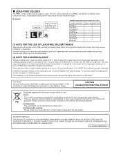
...for details on the soldering iron tip, it is about 220˚C, which may cause a breakdown or anaccident. PLEASE CONTACT YOUR LOCAL SHARP DEALER OR AUTHORIZED SERVICE REPRESENTATIVE FOR ASSISTANCE IN DISPOSING OF THIS BATTERY. Example: 5mm Lead-Free Solder composition code (Refer to the table...PRIMARY (MANGANESS DIOXIDE) MEMORY BACK-UP BATTERY THAT MUST BE DISPOSED OF PROPERLY. The "LF" marks indicated on the PWB's and the Service Manual mean "Lead-Free" solder. This may corrode easily. For EU: The crossed-out wheeled bin implies that of conventional lead solder, and its...
...for details on the soldering iron tip, it is about 220˚C, which may cause a breakdown or anaccident. PLEASE CONTACT YOUR LOCAL SHARP DEALER OR AUTHORIZED SERVICE REPRESENTATIVE FOR ASSISTANCE IN DISPOSING OF THIS BATTERY. Example: 5mm Lead-Free Solder composition code (Refer to the table...PRIMARY (MANGANESS DIOXIDE) MEMORY BACK-UP BATTERY THAT MUST BE DISPOSED OF PROPERLY. The "LF" marks indicated on the PWB's and the Service Manual mean "Lead-Free" solder. This may corrode easily. For EU: The crossed-out wheeled bin implies that of conventional lead solder, and its...

Service Manual
Page 8
... holds authorship rights to work. gram. n Setup Manual: 1 n Vertical sticker (Operation panel): 1 n Vertical sticker (Logo): 1 n USB flash drive cover: 1 n USB flash drive cover screw (+): 1 (PN-T321) n USB flash drive cover screw (-): 1 (PN-T322B) n Cover Sharp logo: 1 Place this sticker onto the SHARP logo to VESA DPMS and DVI DMPM. PN-T321/T322B OUTLINE OF THE PRODUCT 1 - 4 POWER MANAGEMENT...
... holds authorship rights to work. gram. n Setup Manual: 1 n Vertical sticker (Operation panel): 1 n Vertical sticker (Logo): 1 n USB flash drive cover: 1 n USB flash drive cover screw (+): 1 (PN-T321) n USB flash drive cover screw (-): 1 (PN-T322B) n Cover Sharp logo: 1 Place this sticker onto the SHARP logo to VESA DPMS and DVI DMPM. PN-T321/T322B OUTLINE OF THE PRODUCT 1 - 4 POWER MANAGEMENT...
Service Manual
Page 13
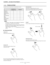
...-AND-HOLD*1 Same action as left-clicking a mouse. If there is selected in Touch Screen Calibration Utility.For details, see the Touch Panel Driver Operation Manual. 3Refer to use. n In Windows XP/Vista, press and hold Pan Zoom Press-and-tap Rotation Windows XP / Windows Vista o o o Windows 7 o o o o o o o o o MEMO n In Windows... take place. CHAPTER 1. TOUCH ACTION Operations that can be performed vary depending on the OS. Press briefly with a mouse. OUTLINE OF THE PRODUCT 2 - 2. PN-T321/T322B OUTLINE OF THE PRODUCT 1 - 9 When you want to page 2 - 11 "3 - 3.
...-AND-HOLD*1 Same action as left-clicking a mouse. If there is selected in Touch Screen Calibration Utility.For details, see the Touch Panel Driver Operation Manual. 3Refer to use. n In Windows XP/Vista, press and hold Pan Zoom Press-and-tap Rotation Windows XP / Windows Vista o o o Windows 7 o o o o o o o o o MEMO n In Windows... take place. CHAPTER 1. TOUCH ACTION Operations that can be performed vary depending on the OS. Press briefly with a mouse. OUTLINE OF THE PRODUCT 2 - 2. PN-T321/T322B OUTLINE OF THE PRODUCT 1 - 9 When you want to page 2 - 11 "3 - 3.
Service Manual
Page 17
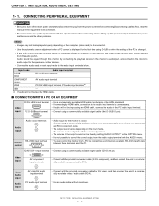
...monitor is unnecessary. PC/AV DVI-D input terminal n Connect using a commercially available signal cable (Mini D-SUB 15 pin). Also, read the manual of the PC is displayed for the first time using a commercially available 3.5 mm mini stereo jack cable or a 3.5 mm mini stereo jack... audio used in each input mode to be fixed by connecting a commercially available RS-232 straight cable between these terminals and the PC. PN-T321/T322B INSTALLATION, ADJUSTMENT, SETTING 2 - 2 Audio should be adjusted with the output terminal when connecting cables. n The volume of the output ...
...monitor is unnecessary. PC/AV DVI-D input terminal n Connect using a commercially available signal cable (Mini D-SUB 15 pin). Also, read the manual of the PC is displayed for the first time using a commercially available 3.5 mm mini stereo jack cable or a 3.5 mm mini stereo jack... audio used in each input mode to be fixed by connecting a commercially available RS-232 straight cable between these terminals and the PC. PN-T321/T322B INSTALLATION, ADJUSTMENT, SETTING 2 - 2 Audio should be adjusted with the output terminal when connecting cables. n The volume of the output ...
Service Manual
Page 19
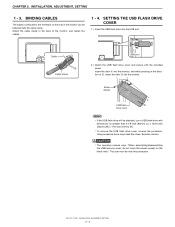
...Screw 3 (black) 3 USB flash drive cover 1 2 MEMO n If the USB flash drive will be note this precaution. PN-T321/T322B INSTALLATION, ADJUSTMENT, SETTING 2 - 4 BINDING CABLES The cables connected to the back of the monitor can be fastened with the ...provided screw. Cable Cable clamp USB port 2 ) Attach the USB flash drive cover and secure with the cable clamp. Using excessive force may break the claws. CAUTION n The operation manual...
...Screw 3 (black) 3 USB flash drive cover 1 2 MEMO n If the USB flash drive will be note this precaution. PN-T321/T322B INSTALLATION, ADJUSTMENT, SETTING 2 - 4 BINDING CABLES The cables connected to the back of the monitor can be fastened with the ...provided screw. Cable Cable clamp USB port 2 ) Attach the USB flash drive cover and secure with the cable clamp. Using excessive force may break the claws. CAUTION n The operation manual...

Service Manual
Page 20
Adjust the screen automatically or manually. 2 - 1. Try manual adjustment if necessary. 4 ) When adjustment is finished, press the [Esc] on the computer's keyboard to brighten the entire screen. INITIALIZATION (RESET...seconds. 5 ) Press twice to the specifications of the PC, use the automatic screen adjustment. 1 ) Switch the input to be adjusted properly with e and d.) PN-T321/T322B INSTALLATION, ADJUSTMENT, SETTING 2 - 5 CHAPTER 2. The automatic adjustment is complete in the [Monitor] folder. INSTALLATION, ADJUSTMENT, SETTING 2. OPENING THE ADJUSTMENT PATTERN The following...
Adjust the screen automatically or manually. 2 - 1. Try manual adjustment if necessary. 4 ) When adjustment is finished, press the [Esc] on the computer's keyboard to brighten the entire screen. INITIALIZATION (RESET...seconds. 5 ) Press twice to the specifications of the PC, use the automatic screen adjustment. 1 ) Switch the input to be adjusted properly with e and d.) PN-T321/T322B INSTALLATION, ADJUSTMENT, SETTING 2 - 5 CHAPTER 2. The automatic adjustment is complete in the [Monitor] folder. INSTALLATION, ADJUSTMENT, SETTING 2. OPENING THE ADJUSTMENT PATTERN The following...
Service Manual
Page 50
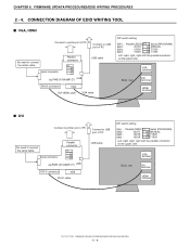
...VGA DVI-HDMI cable VGA cable DIP switch setting SW1 : Parallel (EDID) SW2 : AUTO SW3 : 1502A SW4 : 1502A Serial (PROGRAM) MANUAL T1620 T1620 Left, right, right, right with the parallel connector on the upper side. Parallel connector Serial connector Jig PWB (X1049MP-27) ...-D connector VGA DVI-D cable USB cable DIP switch setting SW1 : Parallel (EDID) SW2 : AUTO SW3 : 1502A SW4 : 1502A Serial (PROGRAM) MANUAL T1620 T1620 Left, right, right, right with the parallel connector on the upper side. CHAPTER 6. FIRMWARE UPDATA PROCEDURES/EDID WRITING PROCEDURES 2 - 4....
...VGA DVI-HDMI cable VGA cable DIP switch setting SW1 : Parallel (EDID) SW2 : AUTO SW3 : 1502A SW4 : 1502A Serial (PROGRAM) MANUAL T1620 T1620 Left, right, right, right with the parallel connector on the upper side. Parallel connector Serial connector Jig PWB (X1049MP-27) ...-D connector VGA DVI-D cable USB cable DIP switch setting SW1 : Parallel (EDID) SW2 : AUTO SW3 : 1502A SW4 : 1502A Serial (PROGRAM) MANUAL T1620 T1620 Left, right, right, right with the parallel connector on the upper side. CHAPTER 6. FIRMWARE UPDATA PROCEDURES/EDID WRITING PROCEDURES 2 - 4....

