
PNG655U Operation Manual
Page 3
ENGLISH PN-G655U LCD MONITOR ENGLISH IMPORTANT: To aid reporting in case of important operating and maintenance (servicing) instructions in the literature accompanying the product. REFER SERVICING TO QUALIFIED SERVICE PERSONNEL. Model No.: Serial No.: U.S.A. CAUTION: The AC outlet shall be installed near the equipment and shall be of sufficient magnitude to persons. NO USER-SERVICEABLE PARTS INSIDE. CAUTION RISK OF ELECTRIC SHOCK DO...
ENGLISH PN-G655U LCD MONITOR ENGLISH IMPORTANT: To aid reporting in case of important operating and maintenance (servicing) instructions in the literature accompanying the product. REFER SERVICING TO QUALIFIED SERVICE PERSONNEL. Model No.: Serial No.: U.S.A. CAUTION: The AC outlet shall be installed near the equipment and shall be of sufficient magnitude to persons. NO USER-SERVICEABLE PARTS INSIDE. CAUTION RISK OF ELECTRIC SHOCK DO...

PNG655U Operation Manual
Page 5
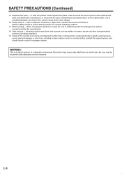
... power cord from the AC outlet, and request a qualified service person to perform many years of trouble-free operation of your LCD product, please read the following precautions carefully before using the product. 1. Read instructions - These safety and operating instructions must be routed properly to clean the product. Use a dry cloth to prevent people from stepping on them . 10. Use of a SHARP LCD...
... power cord from the AC outlet, and request a qualified service person to perform many years of trouble-free operation of your LCD product, please read the following precautions carefully before using the product. 1. Read instructions - These safety and operating instructions must be routed properly to clean the product. Use a dry cloth to prevent people from stepping on them . 10. Use of a SHARP LCD...
PNG655U Operation Manual
Page 6
... away from heat sources such as the original parts. WARNING: This is in proper operating condition. 17. Upon completion of the monitor must not be accompanied by the manufacturer. 18. When mounting the product on a wall, be required to death, personal injury, severe physical damage or other danger. 16. Usage of service or repair work, request the service technician to...
... away from heat sources such as the original parts. WARNING: This is in proper operating condition. 17. Upon completion of the monitor must not be accompanied by the manufacturer. 18. When mounting the product on a wall, be required to death, personal injury, severe physical damage or other danger. 16. Usage of service or repair work, request the service technician to...
PNG655U Operation Manual
Page 7
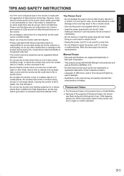
... in this happens, please turn off the main power switch of Microsoft Corporation. - Illustrations in unsafe places. Do not place the monitor on again to the service representative. Causing the monitor to fire. - Use only the power cord supplied with wet hands. Do not remove or insert the power plug with the monitor. - Refer the servicing to confirm operation. 5E Microsoft and Windows...
... in this happens, please turn off the main power switch of Microsoft Corporation. - Illustrations in unsafe places. Do not place the monitor on again to the service representative. Causing the monitor to fire. - Use only the power cord supplied with wet hands. Do not remove or insert the power plug with the monitor. - Refer the servicing to confirm operation. 5E Microsoft and Windows...
PNG655U Operation Manual
Page 8
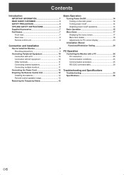
... AND SAFETY INSTRUCTIONS 5 Supplied Accessories 7 Part Names 7 Front view 7 Rear view 8 Remote control unit 8 Connection and Installation How to Install the Monitor 9 Mounting precautions 9 Connecting Peripheral Equipment 10 Connection with a PC 10 Connection with AV equipment 10 Other terminals 11 Connecting external speakers 11 Connecting multiple monitors 11 Connecting the Power Cord 12 Preparing the Remote Control Unit 12 Installing the batteries 12 Remote control operation range 12 Removing the Temporary Stand 13 Basic Operation Turning Power On/Off 14 Turning on the...
... AND SAFETY INSTRUCTIONS 5 Supplied Accessories 7 Part Names 7 Front view 7 Rear view 8 Remote control unit 8 Connection and Installation How to Install the Monitor 9 Mounting precautions 9 Connecting Peripheral Equipment 10 Connection with a PC 10 Connection with AV equipment 10 Other terminals 11 Connecting external speakers 11 Connecting multiple monitors 11 Connecting the Power Cord 12 Preparing the Remote Control Unit 12 Installing the batteries 12 Remote control operation range 12 Removing the Temporary Stand 13 Basic Operation Turning Power On/Off 14 Turning on the...
PNG655U Operation Manual
Page 11
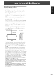
... and the work might be used at least 4 times or more the weight of the monitor. Please note that this is carried out by at the top of this stand is for temporary use only until the monitor is properly mounted. • Be sure to use a stand or a wall-mount bracket designed or designated for accidents or injuries caused by an authorized SHARP dealer. If...
... and the work might be used at least 4 times or more the weight of the monitor. Please note that this is carried out by at the top of this stand is for temporary use only until the monitor is properly mounted. • Be sure to use a stand or a wall-mount bracket designed or designated for accidents or injuries caused by an authorized SHARP dealer. If...
PNG655U Operation Manual
Page 12
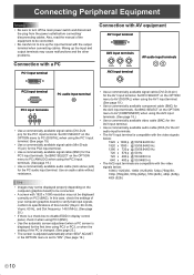
... OPTION menu to disable EDID in display control panel, check it when using PC3 (BNC). • Use the automatic screen adjustment when a PC screen is set to turn off the main power switch and disconnect the plug from the power outlet before connecting/ disconnecting cables. Set DVI SELECT on the OPTION menu to mix up the input and output terminals may cause malfunctions and the other problems. Connection with a PC PC1 input terminal Connection with the video signals...
... OPTION menu to disable EDID in display control panel, check it when using PC3 (BNC). • Use the automatic screen adjustment when a PC screen is set to turn off the main power switch and disconnect the plug from the power outlet before connecting/ disconnecting cables. Set DVI SELECT on the OPTION menu to mix up the input and output terminals may cause malfunctions and the other problems. Connection with a PC PC1 input terminal Connection with the video signals...
PNG655U Operation Manual
Page 13
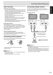
....) Digital signal (DVI) cables (commercially available) Connecting external speakers Be sure to use external speakers with an impedance of 6 Ω and a rated input of this case, turn off the power to all the monitors connected in a daisy chain via DVI cable (commercially available). (See the description on the input mode selection. (See page 15.) • The volume level can be adjusted using the volume adjustment. (See page 15.) • Selecting FIXED of "AUDIO OUTPUT" from...
....) Digital signal (DVI) cables (commercially available) Connecting external speakers Be sure to use external speakers with an impedance of 6 Ω and a rated input of this case, turn off the power to all the monitors connected in a daisy chain via DVI cable (commercially available). (See the description on the input mode selection. (See page 15.) • The volume level can be adjusted using the volume adjustment. (See page 15.) • Selecting FIXED of "AUDIO OUTPUT" from...

PNG655U Operation Manual
Page 14
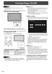
Main power switch 1 2 AC input terminal Power outlet 3 Power cord (Supplied) Preparing the Remote Control Unit Installing the batteries 1. Press the cover gently and slide it in an area with high humidity. • The remote control unit may not work properly if the remote control sensor is under direct sunlight or strong lighting. • Objects between the remote control unit and the remote control sensor may prevent proper operation. • Replace the batteries when they...
Main power switch 1 2 AC input terminal Power outlet 3 Power cord (Supplied) Preparing the Remote Control Unit Installing the batteries 1. Press the cover gently and slide it in an area with high humidity. • The remote control unit may not work properly if the remote control sensor is under direct sunlight or strong lighting. • Objects between the remote control unit and the remote control sensor may prevent proper operation. • Replace the batteries when they...

PNG655U Operation Manual
Page 15
... devices. 13 E Please note that this monitor. ENGLISH Removing the Temporary Stand Prepare wall-hanging brackets or a stand to the temporary stand when shipped from falling down, and remove the stand fixing screws (4). (Rear view) 2. Do not use for temporary use only until the monitor is heavy. When the installation is complete, attach the included stand hole protection covers, using the supplied screws. (1) Fold the sheet perpendicularly with the...
... devices. 13 E Please note that this monitor. ENGLISH Removing the Temporary Stand Prepare wall-hanging brackets or a stand to the temporary stand when shipped from falling down, and remove the stand fixing screws (4). (Rear view) 2. Do not use for temporary use only until the monitor is heavy. When the installation is complete, attach the included stand hole protection covers, using the supplied screws. (1) Fold the sheet perpendicularly with the...
PNG655U Operation Manual
Page 16
... power switch of the monitor Power "On" Power "Off" (Standby mode) Input signal standby mode (input using a PC) Caution • When switching the main power switch or the POWER button off and back on the remote control unit. Set the ADJUSTMENT LOCK in a malfunction. DATE/TIME SETTING // : : SET 20 07 / 01 / 01 00 : 00 When the main power switch is first turned on the remote control unit, the monitor enters standby mode. • You can turn the power ON/OFF. INPUT Status of a power LED Green lighting Orange lighting Green flashing Power LED...
... power switch of the monitor Power "On" Power "Off" (Standby mode) Input signal standby mode (input using a PC) Caution • When switching the main power switch or the POWER button off and back on the remote control unit. Set the ADJUSTMENT LOCK in a malfunction. DATE/TIME SETTING // : : SET 20 07 / 01 / 01 00 : 00 When the main power switch is first turned on the remote control unit, the monitor enters standby mode. • You can turn the power ON/OFF. INPUT Status of a power LED Green lighting Orange lighting Green flashing Power LED...
PNG655U Operation Manual
Page 17
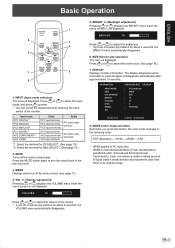
...). Input mode PC1 DIGITAL*1 PC2 ANALOG PC3 ANALOG*2 AV1 DIGITAL*1 AV2 COMPONENT*2 AV3 VIDEO Video PC1 input terminal PC2 input terminal PC3 input terminals AV1 input terminal AV2 input terminals AV3 input terminal Audio PC audio input terminal AV audio input terminals *1 Select the terminal for DVI SELECT. (See page 19.) *2 Select the terminal for about 4 seconds, the BRIGHT menu automatically disappears. 6. MENU Displays and turns off the volume temporarily. The display disappears when this button, the color mode changes...
...). Input mode PC1 DIGITAL*1 PC2 ANALOG PC3 ANALOG*2 AV1 DIGITAL*1 AV2 COMPONENT*2 AV3 VIDEO Video PC1 input terminal PC2 input terminal PC3 input terminals AV1 input terminal AV2 input terminals AV3 input terminal Audio PC audio input terminal AV audio input terminals *1 Select the terminal for DVI SELECT. (See page 19.) *2 Select the terminal for about 4 seconds, the BRIGHT menu automatically disappears. 6. MENU Displays and turns off the volume temporarily. The display disappears when this button, the color mode changes...
PNG655U Operation Manual
Page 19
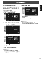
... menu screen will close in gray. (e.g. ENGLISH Menu Items Displaying the menu screen Video and audio adjustment and settings of input signal, and other data. Function not supported by the current input signal) 4. SCREEN SCREEN PICTURE AUDIO SETUP OPTION ENLARGE AUTO CLOCK PHASE H-POS V-POS RESET PIP/PbyP 1024x768 1/1 PC2 ANALOG 127 31 150 31 V: 60 Hz H: 48.4 kHz END···[MENU] 2. TIPS • Items that have press . SCREEN PICTURE 1/2 PC2 ANALOG PICTURE AUTO AUDIO CONTRAST 40 SETUP BLACK LEVEL 96 OPTION SHARPNESS...
... menu screen will close in gray. (e.g. ENGLISH Menu Items Displaying the menu screen Video and audio adjustment and settings of input signal, and other data. Function not supported by the current input signal) 4. SCREEN SCREEN PICTURE AUDIO SETUP OPTION ENLARGE AUTO CLOCK PHASE H-POS V-POS RESET PIP/PbyP 1024x768 1/1 PC2 ANALOG 127 31 150 31 V: 60 Hz H: 48.4 kHz END···[MENU] 2. TIPS • Items that have press . SCREEN PICTURE 1/2 PC2 ANALOG PICTURE AUTO AUDIO CONTRAST 40 SETUP BLACK LEVEL 96 OPTION SHARPNESS...

PNG655U Operation Manual
Page 20
... of the audio sound between right and left. E 18 Select "ON" and then press MENU . PICTURE AUTO (PC2/PC3) The CONTRAST and BLACK LEVEL are flickers at corners. PRESET Selects the color temperature when the WHITE BALANCE is set to USER. G-CONTRAST Adjusts green component when the WHITE BALANCE is set to PRESET. BALANCE Adjusts the balance of the PICTURE menu items to USER. When using the adjustment pattern (see...
... of the audio sound between right and left. E 18 Select "ON" and then press MENU . PICTURE AUTO (PC2/PC3) The CONTRAST and BLACK LEVEL are flickers at corners. PRESET Selects the color temperature when the WHITE BALANCE is set to USER. G-CONTRAST Adjusts green component when the WHITE BALANCE is set to PRESET. BALANCE Adjusts the balance of the PICTURE menu items to USER. When using the adjustment pattern (see...

PNG655U Operation Manual
Page 21
... AUTO is selected, the color system is activated, the power LED flashes (at approx. 1 second interval) in a daisy chain (see page 26), using VOLUME. ENGLISH Menu Items SCREEN MOTION Residual images are available for the menu screen. PATTERN 1 .... A black screen spreads from the PC/AV audio output terminals. A black bar moves from no ID number is displayed. 19 E When this as the state where no signal to the input signal standby mode...
... AUTO is selected, the color system is activated, the power LED flashes (at approx. 1 second interval) in a daisy chain (see page 26), using VOLUME. ENGLISH Menu Items SCREEN MOTION Residual images are available for the menu screen. PATTERN 1 .... A black screen spreads from the PC/AV audio output terminals. A black bar moves from no ID number is displayed. 19 E When this as the state where no signal to the input signal standby mode...

PNG655U Operation Manual
Page 22
... Adjust the horizontal position of the enlarged screen. PIP/PbyP PIP MODES Sets the display method. PbyP2 ......Displays a main screen which is output in a line. SOUND CHANGE Sets the sound which measures 1280 pixels in the longest direction and a sub screen in PIP, PbyP, or PbyP2 mode. AUTO OFF Sets the display method when no signals for the sub screen are input in the PIP/PbyP menu. MANUAL....... Displays a main screen and a black sub screen. Set this menu item to THRU, BLACK...
... Adjust the horizontal position of the enlarged screen. PIP/PbyP PIP MODES Sets the display method. PbyP2 ......Displays a main screen which is output in a line. SOUND CHANGE Sets the sound which measures 1280 pixels in the longest direction and a sub screen in PIP, PbyP, or PbyP2 mode. AUTO OFF Sets the display method when no signals for the sub screen are input in the PIP/PbyP menu. MANUAL....... Displays a main screen and a black sub screen. Set this menu item to THRU, BLACK...

PNG655U Operation Manual
Page 24
... power LED alternately in red and orange in standby mode. • A SCHEDULE that has a large number has precedence over that the set the time to switch the monitor on video. Set the SCHEDULE. (See the description below.) Press or to select the date and time, and press or to perform 3-dimension Y/C separation. MENU SCHEDULE becomes effective. (1) ●: SCHEDULE effective -: SCHEDULE not effective (2) POWER ON : Switches the monitor on . Setting...
... power LED alternately in red and orange in standby mode. • A SCHEDULE that has a large number has precedence over that the set the time to switch the monitor on video. Set the SCHEDULE. (See the description below.) Press or to select the date and time, and press or to perform 3-dimension Y/C separation. MENU SCHEDULE becomes effective. (1) ●: SCHEDULE effective -: SCHEDULE not effective (2) POWER ON : Switches the monitor on . Setting...
PNG655U Operation Manual
Page 35
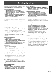
... monitor's remote control sensor. (See page 12.) • Is the menu display hidden or is operation disabled? (See page 24.) Sound from only one side. • Are audio cables connected properly? (See pages 10 and 11.) • Make sure audio cables for external speakers are connected in a daisy chain, turn off and then back on again. • If the monitors are connected properly: left and right speakers is reversed. Power LED flashes red...
... monitor's remote control sensor. (See page 12.) • Is the menu display hidden or is operation disabled? (See page 24.) Sound from only one side. • Are audio cables connected properly? (See pages 10 and 11.) • Make sure audio cables for external speakers are connected in a daisy chain, turn off and then back on again. • If the monitors are connected properly: left and right speakers is reversed. Power LED flashes red...
PNG655U Operation Manual
Page 36
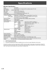
... protrusions) Approx. 143.3 (65) (excluding the temporary stand) *1 Cannot be some deviations from these values in individual units. resolution (pixels) Max. There may be used simultaneously. *2 Does not support plug and play Power management Input terminals Output terminals Power requirement Operating temperature Operating humidity Power consumption Dimensions inch (mm) Weight lbs. (kg) PN-G655U 65" wide (163.9 cm diagonal) ASV low-reflection black TFT LCD 1920 x 1080 16.77 M colors (8 bits/color) 0.744 mm...
... protrusions) Approx. 143.3 (65) (excluding the temporary stand) *1 Cannot be some deviations from these values in individual units. resolution (pixels) Max. There may be used simultaneously. *2 Does not support plug and play Power management Input terminals Output terminals Power requirement Operating temperature Operating humidity Power consumption Dimensions inch (mm) Weight lbs. (kg) PN-G655U 65" wide (163.9 cm diagonal) ASV low-reflection black TFT LCD 1920 x 1080 16.77 M colors (8 bits/color) 0.744 mm...

PNG655U Operation Manual
Page 37
...;Compatible signal timing (PC) Screen resolution VESA 640 x 480 800 x 600 848 x 480 1024 x 768 Wide US TEXT Sun 1152 x 864 1280 x 768 1280 x 960 1280 x 1024 1360 x 768 1600 x 1200*1 1280 x 720 1920 x 1080 720 x 400 1024 x 768 1152 x 900 1280 x 1024 1600 x 1000 *1 Displays a reduced image. Yes - Note that screw hole depth of thread. SHARP recommends using mounting interface...
...;Compatible signal timing (PC) Screen resolution VESA 640 x 480 800 x 600 848 x 480 1024 x 768 Wide US TEXT Sun 1152 x 864 1280 x 768 1280 x 960 1280 x 1024 1360 x 768 1600 x 1200*1 1280 x 720 1920 x 1080 720 x 400 1024 x 768 1152 x 900 1280 x 1024 1600 x 1000 *1 Displays a reduced image. Yes - Note that screw hole depth of thread. SHARP recommends using mounting interface...


