
Service Manual
Page 1
... and only parts identical to those specified should be used . TopPage SUPPLEMENT ATTACHED LC-52D43U SERVICE MANUAL No. For other technical information, refer to change without notice. S87P2LC52D43U LCD COLOR TELEVISION MODEL LC-52D43U In the interests of user-safety (Required by safety regulations in some countries) the set . OPERATION MANUAL [1] SPECIFICATIONS 1-1 [2] OPERATION MANUAL 1-2 [3] DIMENSIONS 1-8 CHAPTER 2. OVERALL WIRING DIAGRAM/BLOCK DIAGRAM [1] OVERALL WIRING DIAGRAM 5-1 [2] SYSTEM BLOCK DIAGRAM 5-3 CHAPTER 6. SCHEMATIC DIAGRAM [1] DESCRIPTION OF SCHEMATIC DIA...
... and only parts identical to those specified should be used . TopPage SUPPLEMENT ATTACHED LC-52D43U SERVICE MANUAL No. For other technical information, refer to change without notice. S87P2LC52D43U LCD COLOR TELEVISION MODEL LC-52D43U In the interests of user-safety (Required by safety regulations in some countries) the set . OPERATION MANUAL [1] SPECIFICATIONS 1-1 [2] OPERATION MANUAL 1-2 [3] DIMENSIONS 1-8 CHAPTER 2. OVERALL WIRING DIAGRAM/BLOCK DIAGRAM [1] OVERALL WIRING DIAGRAM 5-1 [2] SYSTEM BLOCK DIAGRAM 5-3 CHAPTER 6. SCHEMATIC DIAGRAM [1] DESCRIPTION OF SCHEMATIC DIA...

Service Manual
Page 2
... QJAKEA073WJZZ - LC-52D43U LOCU52DT4L3UINE AND MODIFIED PARTS LIST Service Manual OUTLINE This Service Manual covers the differences from LC-32/37D42U. Description PRINTED WIRING BOARD ASSEMBLIES R/C, LED Unit KEY Unit AV TERMINAL Unit MAIN Unit POWER Unit LC-32D42U/37D42U (Base Model) LC-52D43U DUNTKD909FM02 DUNTKD910FM02 DUNTKD999FM04 DUNTKD862FM04 RDENCA198WJQZ DUNTKD909FM02 DUNTKD910FM02 DUNTKD935FM02 DUNTKD862FM07 RDENCA184WJQZ Remark No Change No Change Change Change Unit Replacement Item LCD PANEL (NOTE: THE PARTS HERE SHOWN ARE SUPPLIED AS AN ASSEMBLY BUT...
... QJAKEA073WJZZ - LC-52D43U LOCU52DT4L3UINE AND MODIFIED PARTS LIST Service Manual OUTLINE This Service Manual covers the differences from LC-32/37D42U. Description PRINTED WIRING BOARD ASSEMBLIES R/C, LED Unit KEY Unit AV TERMINAL Unit MAIN Unit POWER Unit LC-32D42U/37D42U (Base Model) LC-52D43U DUNTKD909FM02 DUNTKD910FM02 DUNTKD999FM04 DUNTKD862FM04 RDENCA198WJQZ DUNTKD909FM02 DUNTKD910FM02 DUNTKD935FM02 DUNTKD862FM07 RDENCA184WJQZ Remark No Change No Change Change Change Unit Replacement Item LCD PANEL (NOTE: THE PARTS HERE SHOWN ARE SUPPLIED AS AN ASSEMBLY BUT...
Service Manual
Page 5
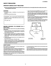
... 10W 3. TO EXPOSED METAL PARTS CONNECT TO KNOWN EARTH GROUND SAFETY NOTICE Many electrical and mechanical parts in the receiver. 4. electrical components having with 5000 ohm per volt, or higher, sensitivity or measure the AC voltage drop across the resistor. LSCA52FD4E3UTY PRECAUTION Service Manual LC-52D43U IMPORTANT SERVICE SAFETY PRECAUTION Service work should be identical to those used only for the purpose of...
... 10W 3. TO EXPOSED METAL PARTS CONNECT TO KNOWN EARTH GROUND SAFETY NOTICE Many electrical and mechanical parts in the receiver. 4. electrical components having with 5000 ohm per volt, or higher, sensitivity or measure the AC voltage drop across the resistor. LSCA52FD4E3UTY PRECAUTION Service Manual LC-52D43U IMPORTANT SERVICE SAFETY PRECAUTION Service work should be identical to those used only for the purpose of...

Service Manual
Page 8
LC-52D43U [2] OPERATION MANUAL Part names TV (Front) NOTE *OPC: Optical Picture Control. **TV status indicator. TV (Rear/Top) HDMI terminal (INPUT 4) HDMI terminal (INPUT 5) PC IN terminals (INPUT 6) Antenna/Cable in AUDIO terminals (INPUT 5) DIGITAL AUDIO OUTPUT terminal INPUT 3 terminals Remote control sensor OPC sensor* OPC indicator** SLEEP indicator** POWER indicator** Channel buttons (CH / ) Volume buttons (VOL / ) INPUT button POWER button INPUT 1 terminals INPUT 2 terminals AUDIO OUTPUT terminals AC INPUT terminal 1 - 2
LC-52D43U [2] OPERATION MANUAL Part names TV (Front) NOTE *OPC: Optical Picture Control. **TV status indicator. TV (Rear/Top) HDMI terminal (INPUT 4) HDMI terminal (INPUT 5) PC IN terminals (INPUT 6) Antenna/Cable in AUDIO terminals (INPUT 5) DIGITAL AUDIO OUTPUT terminal INPUT 3 terminals Remote control sensor OPC sensor* OPC indicator** SLEEP indicator** POWER indicator** Channel buttons (CH / ) Volume buttons (VOL / ) INPUT button POWER button INPUT 1 terminals INPUT 2 terminals AUDIO OUTPUT terminals AC INPUT terminal 1 - 2

Service Manual
Page 9
...: Display captions from a closed-caption source. 27 AV MODE: Select an audio or video setting. (When the input source is INPUT 4, 5 or 6: STANDARD, MOVIE, GAME, PC, USER, DYNAMIC (Fixed), DYNAMIC) 1 - 3 This button is used for TV, CBL/SAT, VCR, DVD and AUDIO operation. Press again to return to the previous channel or external input mode. 19 CH / : Select the channel. 20 MUTE: Mute the sound. 21 MENU: Display the menu screen. 22 / / / /ENTER: Select a desired item on and off the menu screen. 12 SLEEP: Set...
...: Display captions from a closed-caption source. 27 AV MODE: Select an audio or video setting. (When the input source is INPUT 4, 5 or 6: STANDARD, MOVIE, GAME, PC, USER, DYNAMIC (Fixed), DYNAMIC) 1 - 3 This button is used for TV, CBL/SAT, VCR, DVD and AUDIO operation. Press again to return to the previous channel or external input mode. 19 CH / : Select the channel. 20 MUTE: Mute the sound. 21 MENU: Display the menu screen. 22 / / / /ENTER: Select a desired item on and off the menu screen. 12 SLEEP: Set...

Service Manual
Page 11
... cut off . • Is the sleep timer set correctly? Remove any objects blocking vent or clean. • No picture • Is connection to receive broadcast. • No broadcast now. Error code E202 E203 Possible Solution • Check the antenna cable. Cautions regarding use in "Output Select"? • Have you pressed TV POWER on a screen • Failed to other components correct? • Is correct input signal source selected after 1 or 2 minutes...
... cut off . • Is the sleep timer set correctly? Remove any objects blocking vent or clean. • No picture • Is connection to receive broadcast. • No broadcast now. Error code E202 E203 Possible Solution • Check the antenna cable. Cautions regarding use in "Output Select"? • Have you pressed TV POWER on a screen • Failed to other components correct? • Is correct input signal source selected after 1 or 2 minutes...

Service Manual
Page 15
Remove the 18 lock screws 4 and detach the Rear Cabinet. 4 SD Card Cover 1 3 3 2 2 Stand Rear Cabinet LC-52D43U 2 - 1 Remove the 4 lock screws 2 and detach the Stand. 3. REMOVING OF MAJOR PARSTeSrvice Manual [1] REMOVING OF MAJOR PARTS 1. Remove the 5 lock screws 3 . 4. LCC5H2DA43PU TER 2. Detach the SD Card Cover 1 . 2.
Remove the 18 lock screws 4 and detach the Rear Cabinet. 4 SD Card Cover 1 3 3 2 2 Stand Rear Cabinet LC-52D43U 2 - 1 Remove the 4 lock screws 2 and detach the Stand. 3. REMOVING OF MAJOR PARSTeSrvice Manual [1] REMOVING OF MAJOR PARTS 1. Remove the 5 lock screws 3 . 4. LCC5H2DA43PU TER 2. Detach the SD Card Cover 1 . 2.
Service Manual
Page 16
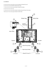
Remove the 4 hook and detach the Stand assist Holder. 7. LC-52D43U 5. Remove the 2 lock screws 7 . 9. Remove the 8 lock screws 6 and detach the Stand Fixing Angle. 8. Remove the 8 lock screws 5 8 lock point and detach the Stand St Cover-R. 6. Remove the 4 lock screws 8 and detach the Bridge Angle and Chassis Fixing Angle. 10.Remove the 7 lock screws 9 and detach the Main Shield. 8 Bridge Angle Bridge Angle 9 Chassis 8 Fixing Angle Main Shield Speaker Speaker 7 7 Stand Fixing Angle 6 6 Hook 5 Lock point Stand Assist Holder Stand St Cover-R Hook 5 Lock point 2 - 2
Remove the 4 hook and detach the Stand assist Holder. 7. LC-52D43U 5. Remove the 2 lock screws 7 . 9. Remove the 8 lock screws 6 and detach the Stand Fixing Angle. 8. Remove the 8 lock screws 5 8 lock point and detach the Stand St Cover-R. 6. Remove the 4 lock screws 8 and detach the Bridge Angle and Chassis Fixing Angle. 10.Remove the 7 lock screws 9 and detach the Main Shield. 8 Bridge Angle Bridge Angle 9 Chassis 8 Fixing Angle Main Shield Speaker Speaker 7 7 Stand Fixing Angle 6 6 Hook 5 Lock point Stand Assist Holder Stand St Cover-R Hook 5 Lock point 2 - 2

Service Manual
Page 18
LC-52D43U 13.Remove the 9 lock screws 11 and detach the Tray Chassis. 14.Disconnect the 3 connectors (MA, FC, SA), and COAXIAL Wire. 15.Remove the 2 lock screws 12 , 3 lock screws 13 , 2 hexagonal shaft for D-sub 14 and detach the Terminal Angle. 16.Remove the 7 lock screws 15 and detach the POWER SUPPLY PWB. 17.Remove the 4 lock screws 16 and detach the AV TERMINAL PWB. 18.Remove the 5 lock screws 17...
LC-52D43U 13.Remove the 9 lock screws 11 and detach the Tray Chassis. 14.Disconnect the 3 connectors (MA, FC, SA), and COAXIAL Wire. 15.Remove the 2 lock screws 12 , 3 lock screws 13 , 2 hexagonal shaft for D-sub 14 and detach the Terminal Angle. 16.Remove the 7 lock screws 15 and detach the POWER SUPPLY PWB. 17.Remove the 4 lock screws 16 and detach the AV TERMINAL PWB. 18.Remove the 5 lock screws 17...
Service Manual
Page 19
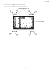
21.Remove the 4 lock screws 21 and detach the LCD Panel Module. 22.Remove the 8 lock screws 22 and detach the Chassis Fixing Angle T/B. Chassis Fixing Angle T/B 22 21 21 22 LC-52D43U LCD Panel Module 22 21 21 22 2 - 5
21.Remove the 4 lock screws 21 and detach the LCD Panel Module. 22.Remove the 8 lock screws 22 and detach the Chassis Fixing Angle T/B. Chassis Fixing Angle T/B 22 21 21 22 LC-52D43U LCD Panel Module 22 21 21 22 2 - 5

Service Manual
Page 20
... "monitor adjustment process" code. AV TERMINAL Unit: DUNTKD935FM01 2. With the strongest color being fixed, KKT10037 turn off ), and make the R and B settings to the optimum conditions at each point Point 5 (This is because the adjustment is required due to part replacement, make the R and B settings to prepare the new units loaded with updated software. AV MODE: [DYNAMIC] Backlight: +16 Aging time: Min. 60 minutes 2) Connect the white...
... "monitor adjustment process" code. AV TERMINAL Unit: DUNTKD935FM01 2. With the strongest color being fixed, KKT10037 turn off ), and make the R and B settings to the optimum conditions at each point Point 5 (This is because the adjustment is required due to part replacement, make the R and B settings to prepare the new units loaded with updated software. AV MODE: [DYNAMIC] Backlight: +16 Aging time: Min. 60 minutes 2) Connect the white...

Service Manual
Page 21
... checking Adjustment procedure 1) Using the checker, write the EDID data for inspection AV MODE: [DYNAMIC] (Reset) Monochrome: ON Black: OFF Color Temp: High Back Light: +16 Aging Time: Min. 60 minutes LC-52D43U 2.2. Adjustment item Adjustment conditions Point 2 LEV20038 (WBI20352) MG2G**** MG2B**** MG2R**** Point 1 LEV10044 (WBI10176) MG1G**** MG1B**** MG1R**** Writing MSET0003 Note Adjustment procedure Set conditions for HDMI to IC1501 and IC1502 that is mounted on...
... checking Adjustment procedure 1) Using the checker, write the EDID data for inspection AV MODE: [DYNAMIC] (Reset) Monochrome: ON Black: OFF Color Temp: High Back Light: +16 Aging Time: Min. 60 minutes LC-52D43U 2.2. Adjustment item Adjustment conditions Point 2 LEV20038 (WBI20352) MG2G**** MG2B**** MG2R**** Point 1 LEV10044 (WBI10176) MG1G**** MG1B**** MG1R**** Writing MSET0003 Note Adjustment procedure Set conditions for HDMI to IC1501 and IC1502 that is mounted on...

Service Manual
Page 26
... (P2703) of IC1404 normal? NO Check IC1404 and peripheral circuits. LC-52D43U LCC5H2DA43PU TER 4. YES Is input signal fed to IC1407 (DSP) normally? YES Are audio outputs of pins 38 and 39 of TERMINAL_UNIT and around the speakers. YES Reset monitor audio output to pins 3 and 5 of IC1401 to "Variable"? YES Are audio output pins 7 and 1 of IC2701. (MUTE circuits: Q1307, Q1314, Q1313...
... (P2703) of IC1404 normal? NO Check IC1404 and peripheral circuits. LC-52D43U LCC5H2DA43PU TER 4. YES Is input signal fed to IC1407 (DSP) normally? YES Are audio outputs of pins 38 and 39 of TERMINAL_UNIT and around the speakers. YES Reset monitor audio output to pins 3 and 5 of IC1401 to "Variable"? YES Are audio output pins 7 and 1 of IC2701. (MUTE circuits: Q1307, Q1314, Q1313...

Service Manual
Page 33
... is heard. YES Check LCD_CONTROL PWB. YES NO Check IC1501 and peripheral circuits. When using an old HDMI transmission device, some video formats cannot be selected or no sound is necessary to upgrade its firmware. YES Are digital video (LVDS) signals sent from IC1507 (TMDS_SW) to input terminals H_RX0± (pins B19 and A19), H_RX1± (pins A18 and B18), H_RX2...
... is heard. YES Check LCD_CONTROL PWB. YES NO Check IC1501 and peripheral circuits. When using an old HDMI transmission device, some video formats cannot be selected or no sound is necessary to upgrade its firmware. YES Are digital video (LVDS) signals sent from IC1507 (TMDS_SW) to input terminals H_RX0± (pins B19 and A19), H_RX1± (pins A18 and B18), H_RX2...

Service Manual
Page 87
... the safety of the set . This document has been published to change without notice. PartsGuide LC-52D43U PARTS GUIDE No. S87P2LC52D43U LCD COLOR TELEVISION MODEL LC-52D43U CONTENTS [1] PRINTED WIRING BOARD ASSEMBLIES [2] LCD PANEL (NOTE: THE PARTS HERE SHOWN ARE SUPPLIED AS AN ASSEMBLY BUT NOT INDEPENDENTLY.) [3] DUNTKD862FM07 (MAIN Unit) (Only changed parts have been described.) [4] DUNTKD935FME02 (TERMINAL Unit) [5] CABINET PARTS [6] SUPPLIED ACCESSORIES [7] PACKING PARTS (NOT REPLACEMENT ITEM) [8] SERVICE JIGS (USE FOR SERVICING) Parts marked with specified ones...
... the safety of the set . This document has been published to change without notice. PartsGuide LC-52D43U PARTS GUIDE No. S87P2LC52D43U LCD COLOR TELEVISION MODEL LC-52D43U CONTENTS [1] PRINTED WIRING BOARD ASSEMBLIES [2] LCD PANEL (NOTE: THE PARTS HERE SHOWN ARE SUPPLIED AS AN ASSEMBLY BUT NOT INDEPENDENTLY.) [3] DUNTKD862FM07 (MAIN Unit) (Only changed parts have been described.) [4] DUNTKD935FME02 (TERMINAL Unit) [5] CABINET PARTS [6] SUPPLIED ACCESSORIES [7] PACKING PARTS (NOT REPLACEMENT ITEM) [8] SERVICE JIGS (USE FOR SERVICING) Parts marked with specified ones...
Service Manual
Page 93
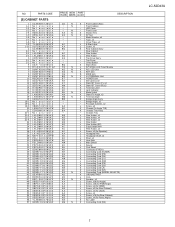
... Sink J Main Shield J Spacer J Cool Sheet J Connector (F-RCA) J Connecting Cord (TUNER) J Connecting Cord (PD) J Connecting Cord (SH) X Connecting Cord (LV) J Connecting Cord (KM) J Connecting Cord (PE) X Connecting Cord (LB) X Connecting Cord LA) X Connecting Cord (SP) X Connecting Cord (MODEL SELECTR) X GROUND-PART J Core X Speaker, x2 J Screw, x28 (for Angle) J Screw, x36 (for PWB/Angle) J Screw, x2 (for HDMI) J Screw, x5 (for Rear Cabinet) J Screw, x3 (for JACK) J Screw, x2 J Screw, x18 (for Rear Cabinet) J Screw, x4 (for Panel Angle) X No. AC AA BQ - AB AB AB AB...
... Sink J Main Shield J Spacer J Cool Sheet J Connector (F-RCA) J Connecting Cord (TUNER) J Connecting Cord (PD) J Connecting Cord (SH) X Connecting Cord (LV) J Connecting Cord (KM) J Connecting Cord (PE) X Connecting Cord (LB) X Connecting Cord LA) X Connecting Cord (SP) X Connecting Cord (MODEL SELECTR) X GROUND-PART J Core X Speaker, x2 J Screw, x28 (for Angle) J Screw, x36 (for PWB/Angle) J Screw, x2 (for HDMI) J Screw, x5 (for Rear Cabinet) J Screw, x3 (for JACK) J Screw, x2 J Screw, x18 (for Rear Cabinet) J Screw, x4 (for Panel Angle) X No. AC AA BQ - AB AB AB AB...

Service Manual
Page 96
... Unit to Speaker-R/-L (SP) J 13pins L=1000mm, Terminal unit to R/C LED Unit (RA) J 12pins L=1000mm, Main Unit to Power Unit (PE) J 6pins L=1000mm, Main Unit to Power Unit (PD) J 30pins L=1000mm, Main Unit to Controller Unit (LV) J 7pins L=1000mm, Main Unit to Controller Unit (SH) 10 LC-52D43U NO. PARTS CODE PRICE NEW PART RANK MARK DELIVERY DESCRIPTION [7] PACKING PARTS (NOT REPLACEMENT ITEM) S1...
... Unit to Speaker-R/-L (SP) J 13pins L=1000mm, Terminal unit to R/C LED Unit (RA) J 12pins L=1000mm, Main Unit to Power Unit (PE) J 6pins L=1000mm, Main Unit to Power Unit (PD) J 30pins L=1000mm, Main Unit to Controller Unit (LV) J 7pins L=1000mm, Main Unit to Controller Unit (SH) 10 LC-52D43U NO. PARTS CODE PRICE NEW PART RANK MARK DELIVERY DESCRIPTION [7] PACKING PARTS (NOT REPLACEMENT ITEM) S1...

Service Manual
Page 99
TopPage LC-52D43U SERVICE MANUAL No. S07V9LC52D43U SUPPLEMENT LCD COLOR TELEVISION MODEL LC-52D43U In the interests of user-safety (Required by safety regulations in the LCD module are subject to those specified should be used . Parts marked with specified ones for maintaining the safety of the set. Be sure to replace these parts with " " are important for maintaining the safety and performance of the set should be restored...
TopPage LC-52D43U SERVICE MANUAL No. S07V9LC52D43U SUPPLEMENT LCD COLOR TELEVISION MODEL LC-52D43U In the interests of user-safety (Required by safety regulations in the LCD module are subject to those specified should be used . Parts marked with specified ones for maintaining the safety of the set. Be sure to replace these parts with " " are important for maintaining the safety and performance of the set should be restored...

Service Manual
Page 100
... LC-52D43U (S87P2LC52D43U) Service Manual. [2] Adjustment When replacing the LCD control PCB, follow these steps to adjust VCOM. 1) Remove the wire from the LCD control PCB CN3. 2) Connect a wire of the VCOM adjustment jig (electronic volume adjustment BOX) to CN3 (see Fig. 1). 3) Turn on the TV set. 4) Turn on the jig (connect to the AC). 5) Enter the process mode to display the item "LCD TEST PATTERN OFF" (see Fig. 2). 6) Press the volume up key once to display a flicker pattern...
... LC-52D43U (S87P2LC52D43U) Service Manual. [2] Adjustment When replacing the LCD control PCB, follow these steps to adjust VCOM. 1) Remove the wire from the LCD control PCB CN3. 2) Connect a wire of the VCOM adjustment jig (electronic volume adjustment BOX) to CN3 (see Fig. 1). 3) Turn on the TV set. 4) Turn on the jig (connect to the AC). 5) Enter the process mode to display the item "LCD TEST PATTERN OFF" (see Fig. 2). 6) Press the volume up key once to display a flicker pattern...

Service Manual
Page 101
S07V9LC52D43U LCD COLOR TELEVISION MODEL LC-52D43U CONTENTS [1] LCD MODULE Assembly Parts marked with specified ones for maintaining the safety of the set . Be sure to replace these parts with " " are subject to be used for after sales service only. This document has been published to change without notice. The contents are important for maintaining the safety and performance of the set . PartsGuide LC-52D43U PARTS GUIDE No.
S07V9LC52D43U LCD COLOR TELEVISION MODEL LC-52D43U CONTENTS [1] LCD MODULE Assembly Parts marked with specified ones for maintaining the safety of the set . Be sure to replace these parts with " " are subject to be used for after sales service only. This document has been published to change without notice. The contents are important for maintaining the safety and performance of the set . PartsGuide LC-52D43U PARTS GUIDE No.


