Service Manual
Page 1
... Service Manual. CONTENTS OUTLINE AND DIFFERENCES FROM BASE MODEL OUTLINE i LIST OF CHANGED PARTS i Parts Guide SAFETY PRECAUTION IMPORTANT SERVICE SAFETY PRECAUTION ii PRECAUTIONS A PRENDRE LORS DE LA REPARATION iii PRECAUTIONS FOR USING LEAD-FREE SOLDER iv PRECAUTIONS IN SERVICING THE HDCPKEY ROM v CHAPTER 1. SPECIFICATIONS [1] SPECIFICATIONS 1-1 CHAPTER 2. This document has been published to the LC-32GP3U-B/W/R (No. OPERATION MANUAL [1] OPERATION MANUAL 2-1 CHAPTER 3. REMOVING OF MAJOR PARTS [1] REMOVING OF MAJOR PARTS 4-1 CHAPTER 5. ADJUSTMENT [1] ADJUSTMENT...
... Service Manual. CONTENTS OUTLINE AND DIFFERENCES FROM BASE MODEL OUTLINE i LIST OF CHANGED PARTS i Parts Guide SAFETY PRECAUTION IMPORTANT SERVICE SAFETY PRECAUTION ii PRECAUTIONS A PRENDRE LORS DE LA REPARATION iii PRECAUTIONS FOR USING LEAD-FREE SOLDER iv PRECAUTIONS IN SERVICING THE HDCPKEY ROM v CHAPTER 1. SPECIFICATIONS [1] SPECIFICATIONS 1-1 CHAPTER 2. This document has been published to the LC-32GP3U-B/W/R (No. OPERATION MANUAL [1] OPERATION MANUAL 2-1 CHAPTER 3. REMOVING OF MAJOR PARTS [1] REMOVING OF MAJOR PARTS 4-1 CHAPTER 5. ADJUSTMENT [1] ADJUSTMENT...
Service Manual
Page 2
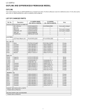
...-1Y VS2SA1162Y/-1Y CABINET AND MECHANICAL PARTS Please refer to a Parts list PACKING PARTS AND ACCESSORIES Please refer to the LC-32GP3U-B/W/R (No. LC-32GP2U LOCU-32TGLP2IUNE AND DIFFERENCES FROM BASE MSOerDvEicLe Manual OUTLINE This model is based on the LC-32GP3U-B/W/R and is changed some parts. This Service Manual covers the modifications alone. S48I7LC32GP2U) DUNTKE264FM02 LCD PANEL LCD Panel Module Unit R1LK315D3LZ20Z R1LK315D3LZ2BZ R/C, LED Unit D103 Diode Q102 Transistor Q103...
...-1Y VS2SA1162Y/-1Y CABINET AND MECHANICAL PARTS Please refer to a Parts list PACKING PARTS AND ACCESSORIES Please refer to the LC-32GP3U-B/W/R (No. LC-32GP2U LOCU-32TGLP2IUNE AND DIFFERENCES FROM BASE MSOerDvEicLe Manual OUTLINE This model is based on the LC-32GP3U-B/W/R and is changed some parts. This Service Manual covers the modifications alone. S48I7LC32GP2U) DUNTKE264FM02 LCD PANEL LCD Panel Module Unit R1LK315D3LZ20Z R1LK315D3LZ2BZ R/C, LED Unit D103 Diode Q102 Transistor Q103...
Service Manual
Page 3
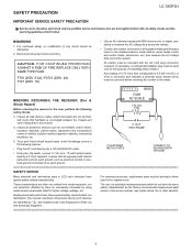
... plug must be repeated with all exposed metal cabinet parts and a known earth ground, such as the factory recommended replacement parts shown in series with 5000 ohm per volt, or higher, sensitivity or measure the AC voltage drop across the resistor. LSCA-32FGEP2TUY PRECAUTION Service Manual LC-32GP2U IMPORTANT SERVICE SAFETY PRECAUTION Service work should be attempted. 2. All checks must be used in LCD color television...
... plug must be repeated with all exposed metal cabinet parts and a known earth ground, such as the factory recommended replacement parts shown in series with 5000 ohm per volt, or higher, sensitivity or measure the AC voltage drop across the resistor. LSCA-32FGEP2TUY PRECAUTION Service Manual LC-32GP2U IMPORTANT SERVICE SAFETY PRECAUTION Service work should be attempted. 2. All checks must be used in LCD color television...
Service Manual
Page 5
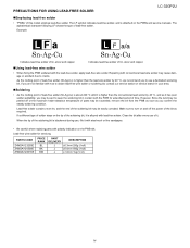
... power of lead-free solder. If a different type of solder stays on the PWBs and service manuals. The alphabetical character following LF shows the type of the bit as it . As the melting point of the soldering bit, it with steel wool or fine sandpaper. • Be careful when replacing parts with lead-free solder. PRECAUTIONS FOR USING LEAD-FREE SOLDER LC-32GP2U...
... power of lead-free solder. If a different type of solder stays on the PWBs and service manuals. The alphabetical character following LF shows the type of the bit as it . As the melting point of the soldering bit, it with steel wool or fine sandpaper. • Be careful when replacing parts with lead-free solder. PRECAUTIONS FOR USING LEAD-FREE SOLDER LC-32GP2U...
Service Manual
Page 6
LC-32GP2U PRECAUTIONS IN SERVICING THE HDCP-KEY ROM Applied part: HDCP-KEY ROM IC8451 RH-IXC318WJQZY (updated ROM) The HDCP-KEY ROM shall be protected and managed for its information inside. In servicing this ROM, therefore, take the following information protection/management measures. 1) When disposing of the component parts and PWBs, destruct the IC itself in a proper way...
LC-32GP2U PRECAUTIONS IN SERVICING THE HDCP-KEY ROM Applied part: HDCP-KEY ROM IC8451 RH-IXC318WJQZY (updated ROM) The HDCP-KEY ROM shall be protected and managed for its information inside. In servicing this ROM, therefore, take the following information protection/management measures. 1) When disposing of the component parts and PWBs, destruct the IC itself in a proper way...
Service Manual
Page 7
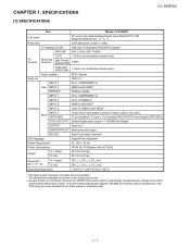
...jack) 75 Unbalance, F Type 1 for Analog (VHF/UHF/CATV) and Digital (AIR/CABLE) DIGITAL AUDIO OUTPUT Optical Digital audio output 1 (PCM/Dolby Digital) OUTPUT Audio out SUBWOOFER PRE OUT Monaural audio output RS-232C 9-pin D-sub male connector OSD language English/French/Spanish Power Requirement AC 120 V, 60 Hz Power Consumption 145 W (0.7 W Standby with HDCP INPUT 7 Rear ANT/CABLE 15-pin mini D-sub female connector, Audio in individual units. 1 - 1 SPECIFICATIONS [1] SPECIFICATIONS Service Manual LC-32GP2U Item Model: LC-32GP2U LCD panel Resolution 32" screen size class...
...jack) 75 Unbalance, F Type 1 for Analog (VHF/UHF/CATV) and Digital (AIR/CABLE) DIGITAL AUDIO OUTPUT Optical Digital audio output 1 (PCM/Dolby Digital) OUTPUT Audio out SUBWOOFER PRE OUT Monaural audio output RS-232C 9-pin D-sub male connector OSD language English/French/Spanish Power Requirement AC 120 V, 60 Hz Power Consumption 145 W (0.7 W Standby with HDCP INPUT 7 Rear ANT/CABLE 15-pin mini D-sub female connector, Audio in individual units. 1 - 1 SPECIFICATIONS [1] SPECIFICATIONS Service Manual LC-32GP2U Item Model: LC-32GP2U LCD panel Resolution 32" screen size class...
Service Manual
Page 8
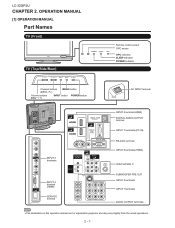
OPERATION MANUAL [1] OPERATION MANUAL Part Names TV (Front) TV (Top/Side/Rear) Service Manual Remote control sensor OPC sensor OPC indicator SLEEP indicator POWER indicator Channel buttons (CH / ) MENU button Volume buttons (VOL / ) INPUT button POWER button AC INPUT terminal INPUT 5 terminal (HDMI) DIGITAL AUDIO OUTPUT terminal INPUT 7 terminals (PC-IN) INPUT 3 terminals INPUT 4 terminal (HDMI) SERVICE terminal RS-232C terminal INPUT 6 terminals (HDMI) Antenna/Cable in SUBWOOFER PRE OUT INPUT 2 terminals INPUT 1 terminals AUDIO OUTPUT terminals The illustrations in this operation ...
OPERATION MANUAL [1] OPERATION MANUAL Part Names TV (Front) TV (Top/Side/Rear) Service Manual Remote control sensor OPC sensor OPC indicator SLEEP indicator POWER indicator Channel buttons (CH / ) MENU button Volume buttons (VOL / ) INPUT button POWER button AC INPUT terminal INPUT 5 terminal (HDMI) DIGITAL AUDIO OUTPUT terminal INPUT 7 terminals (PC-IN) INPUT 3 terminals INPUT 4 terminal (HDMI) SERVICE terminal RS-232C terminal INPUT 6 terminals (HDMI) Antenna/Cable in SUBWOOFER PRE OUT INPUT 2 terminals INPUT 1 terminals AUDIO OUTPUT terminals The illustrations in this operation ...
Service Manual
Page 9
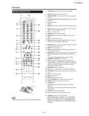
..., VCR, DVD and AUDIO operation. channel audio broadcasts. 17 FUNCTION: Switches the remote control for the current mode. * To enter the code registration mode, you can toggle the selected channels by pressing A, B, C and D. 28 FAVORITE: Set the favorite channels. 29 CC: Display captions from a closed-caption source. 30 AV MODE: Select an audio or video setting. (When the input source is INPUT 4, 5, 6 or 7: STANDARD, MOVIE, GAME, PC, xvYCC (INPUT4/5/6 only), USER, DYNAMIC (Fixed), DYNAMIC) 2 - 2 The lighting will light. LC-32GP2U 1 TV POWER: Switch the TV power on...
..., VCR, DVD and AUDIO operation. channel audio broadcasts. 17 FUNCTION: Switches the remote control for the current mode. * To enter the code registration mode, you can toggle the selected channels by pressing A, B, C and D. 28 FAVORITE: Set the favorite channels. 29 CC: Display captions from a closed-caption source. 30 AV MODE: Select an audio or video setting. (When the input source is INPUT 4, 5, 6 or 7: STANDARD, MOVIE, GAME, PC, xvYCC (INPUT4/5/6 only), USER, DYNAMIC (Fixed), DYNAMIC) 2 - 2 The lighting will light. LC-32GP2U 1 TV POWER: Switch the TV power on...
Service Manual
Page 10
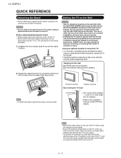
... screws used to turn off the TV. This will not drop from the AC INPUT terminal. Detach the cable clamp on the wall AN-37AG2 wall mount bracket. (See the bracket instructions for details. LC-32GP2U QUICK REFERENCE Detaching the Stand Before attaching (or detaching) the stand, unplug the AC cord from the edge of other wall mount brackets may cause serious injuries. To use this model, make sure to secure the stand...
... screws used to turn off the TV. This will not drop from the AC INPUT terminal. Detach the cable clamp on the wall AN-37AG2 wall mount bracket. (See the bracket instructions for details. LC-32GP2U QUICK REFERENCE Detaching the Stand Before attaching (or detaching) the stand, unplug the AC cord from the edge of other wall mount brackets may cause serious injuries. To use this model, make sure to secure the stand...
Service Manual
Page 11
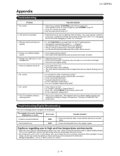
... the remote control sensor? Is connection to 60°C) 2 - 4 Is "Variable" selected in a room that the antenna is not a malfunction. Is the AC cord disconnected? External influences such as picture size made correctly? Is correct input signal source selected after 1 or 2 minutes. Is the correct input selected? Have you pressed TV POWER on the remote control unit. Strange color, light color, or color misalignment. No picture. Set it to change in the program guide. Are screen mode adjustments such...
... the remote control sensor? Is connection to 60°C) 2 - 4 Is "Variable" selected in a room that the antenna is not a malfunction. Is the AC cord disconnected? External influences such as picture size made correctly? Is correct input signal source selected after 1 or 2 minutes. Is the correct input selected? Have you pressed TV POWER on the remote control unit. Strange color, light color, or color misalignment. No picture. Set it to change in the program guide. Are screen mode adjustments such...
Service Manual
Page 12
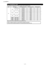
...Resolution Horizontal Frequency 720 x 400 31.5 kHz VGA...formats are registered trademarks of Video Electronics Standards Association. Vertical Frequency 70 Hz 60 Hz 72 Hz 75 Hz 56 Hz 60 Hz 72 Hz 75 Hz 60 Hz 70 Hz 75 Hz 60 Hz 60 Hz 60 Hz 60 Hz DDC is necessary to set the PC correctly to display XGA and WXGA signal. VGA... and XGA are not supported by the analog RGB terminal. LC-32GP2U PC Compatibility Chart It is a registered trademark of International Business Machines Corp. VESA Standard * O O ...
...Resolution Horizontal Frequency 720 x 400 31.5 kHz VGA...formats are registered trademarks of Video Electronics Standards Association. Vertical Frequency 70 Hz 60 Hz 72 Hz 75 Hz 56 Hz 60 Hz 72 Hz 75 Hz 60 Hz 70 Hz 75 Hz 60 Hz 60 Hz 60 Hz 60 Hz DDC is necessary to set the PC correctly to display XGA and WXGA signal. VGA... and XGA are not supported by the analog RGB terminal. LC-32GP2U PC Compatibility Chart It is a registered trademark of International Business Machines Corp. VESA Standard * O O ...
Service Manual
Page 13
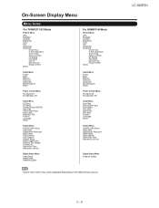
...Power Control Menu No Signal Off No Operation Off Setup Menu Input Skip Select Game Input Input Signal Auto Sync. Position Language Reset Option Menu AQUOS LINK Setup Audio Only Digital Noise Reduction HDMI Setup Output Select Game Play Time Operation Lock Out Digital Setup Menu Software Update Some menu items may not be displayed depending on the selected input source. On-Screen Display Menu Menu Items For TV/INPUT 1/2/3 Mode Picture Menu OPC Backlight Contrast Brightness Color Tint Sharpness Advanced C.M.S.-Hue C.M.S.-Saturation Color Temp. LC-32GP2U 2 - 6 Program Title Display...
...Power Control Menu No Signal Off No Operation Off Setup Menu Input Skip Select Game Input Input Signal Auto Sync. Position Language Reset Option Menu AQUOS LINK Setup Audio Only Digital Noise Reduction HDMI Setup Output Select Game Play Time Operation Lock Out Digital Setup Menu Software Update Some menu items may not be displayed depending on the selected input source. On-Screen Display Menu Menu Items For TV/INPUT 1/2/3 Mode Picture Menu OPC Backlight Contrast Brightness Color Tint Sharpness Advanced C.M.S.-Hue C.M.S.-Saturation Color Temp. LC-32GP2U 2 - 6 Program Title Display...
Service Manual
Page 15
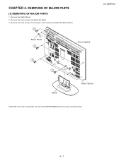
Remove the 4 lock screws and detach the Stand. 3. Remove the 3 lock screws, 2 lock screws, 4 lock screws and detach the Rear Cabinet. 3 1 Black Sheet 3 Front Cabinet LC-32GP2U 3 2 Stand Rear Cabinet CAUTION: In the case of assembly, the new sheet (PSPAGA386WJ00) can be stuck on these screws. 4 - 1 Remove the 3 Black Sheet. 2. REMOVING OF MAJOR PARSTeSrvice Manual [1] REMOVING OF MAJOR PARTS 1. LCC-H32AGPP2UTER 4.
Remove the 4 lock screws and detach the Stand. 3. Remove the 3 lock screws, 2 lock screws, 4 lock screws and detach the Rear Cabinet. 3 1 Black Sheet 3 Front Cabinet LC-32GP2U 3 2 Stand Rear Cabinet CAUTION: In the case of assembly, the new sheet (PSPAGA386WJ00) can be stuck on these screws. 4 - 1 Remove the 3 Black Sheet. 2. REMOVING OF MAJOR PARSTeSrvice Manual [1] REMOVING OF MAJOR PARTS 1. LCC-H32AGPP2UTER 4.
Service Manual
Page 16
Remove the 3 lock screws, 2 lock shaft and detach the Mini AV Shield. 8. Remove the 2 lock screws and detach the SIDE Unit Ass'y. 7. Remove the Top Cover Ass'y. 6. Remove the 2 lock screws and detach the SIDE Unit and Mini AV Key Cover from KEY Unit and SIDE Unit. 5. LC-32GP2U 4. Disconnect the KM, VD, HM, US connectors from the Mini AV Angle. 7 Mini AV Shield 8 4 KM 4 VD HM SIDE Unit US 7 Top Cover 5 Operation Button KEY Unit Mini AV Key Cover 6 Mini AV Angle 4 - 2
Remove the 3 lock screws, 2 lock shaft and detach the Mini AV Shield. 8. Remove the 2 lock screws and detach the SIDE Unit Ass'y. 7. Remove the Top Cover Ass'y. 6. Remove the 2 lock screws and detach the SIDE Unit and Mini AV Key Cover from KEY Unit and SIDE Unit. 5. LC-32GP2U 4. Disconnect the KM, VD, HM, US connectors from the Mini AV Angle. 7 Mini AV Shield 8 4 KM 4 VD HM SIDE Unit US 7 Top Cover 5 Operation Button KEY Unit Mini AV Key Cover 6 Mini AV Angle 4 - 2
Service Manual
Page 17
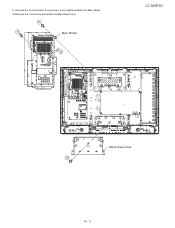
Remove the 10 lock screws, 2 lock screws, 4 lock shaft and detach the Main Shield. 10.Remove the 1 lock screw and detach the Stand Area Cover. 9 9 Main Shield 9 LC-32GP2U Stand Area Cover 10 4 - 3 9.
Remove the 10 lock screws, 2 lock screws, 4 lock shaft and detach the Main Shield. 10.Remove the 1 lock screw and detach the Stand Area Cover. 9 9 Main Shield 9 LC-32GP2U Stand Area Cover 10 4 - 3 9.
Service Manual
Page 18
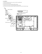
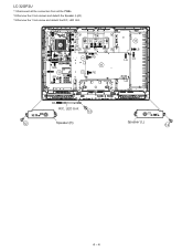
LC-32GP2U 11.Disconnect all the connectors from all the PWBs. 12.Remove the 2 lock screws and detach the Speaker (L)(R). 13.Remove the 1 lock screw and detach the R/C, LED Unit. LP KM LW 11 LB RA PD US HM MA MA VD 11 SP PE PL LP LW PL PD 11 PE 11 LB LA LA RA R/C, LED Unit 13 12 Speaker (R) Speaker (L) 12 4 - 4
LC-32GP2U 11.Disconnect all the connectors from all the PWBs. 12.Remove the 2 lock screws and detach the Speaker (L)(R). 13.Remove the 1 lock screw and detach the R/C, LED Unit. LP KM LW 11 LB RA PD US HM MA MA VD 11 SP PE PL LP LW PL PD 11 PE 11 LB LA LA RA R/C, LED Unit 13 12 Speaker (R) Speaker (L) 12 4 - 4
Service Manual
Page 23
... the safety and performance of the set . MODEL CONTENTS LC-32GP2U [1] PRINTED WIRING BOARD ASSEMBLIES [2] LCD PANEL (NOTE: THE PARTS HERE SHOWN ARE SUPPLIED AS AN ASSEMBLY BUT NOT INDEPENDENTLY.) [3] DUNTKE264FM02 (R/C, LED Unit) [4] DUNTKE373FM02 (MAIN Unit) [5] DUNTKE374FM01 (TERMINAL Unit) [6] NOTE (Conductive cloth tape) [7] CABINET AND MECHANICAL PARTS [8] SUPPLIED ACCESSORIES [9] PACKING PARTS (NOT REPLACEMENT ITEM) [10] SERVICE JIG (USE FOR SERVICING) Parts marked with specified ones for after...
... the safety and performance of the set . MODEL CONTENTS LC-32GP2U [1] PRINTED WIRING BOARD ASSEMBLIES [2] LCD PANEL (NOTE: THE PARTS HERE SHOWN ARE SUPPLIED AS AN ASSEMBLY BUT NOT INDEPENDENTLY.) [3] DUNTKE264FM02 (R/C, LED Unit) [4] DUNTKE373FM02 (MAIN Unit) [5] DUNTKE374FM01 (TERMINAL Unit) [6] NOTE (Conductive cloth tape) [7] CABINET AND MECHANICAL PARTS [8] SUPPLIED ACCESSORIES [9] PACKING PARTS (NOT REPLACEMENT ITEM) [10] SERVICE JIG (USE FOR SERVICING) Parts marked with specified ones for after...
Service Manual
Page 24
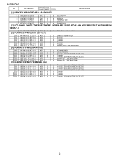
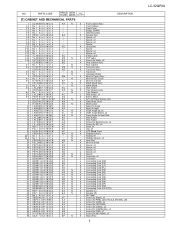
DENTLY.) N R1LK315D3LZ2BZ DS N [3] DUNTKE264FM02 (R/C, LED Unit) J 32" LCD Panel Module Unit D103 RH-PX0421CEZZY AD Q102 VSKTC3875SG-1Y AB Q103 VSKTC3875SG-...-Y(TE85L,F)/(T5L,F,T) 2 LC-32GP2U NO. PARTS CODE PRICE NEW PART RANK MARK DELIVERY DESCRIPTION [1] PRINTED WIRING BOARD ASSEMBLIES N DUNTKE264FM02 N DUNTKE266FM02 N DUNTKE373FM02 N DUNTKE374FM01 N DUNTKE488FM01 N RDENCA257WJQZ AP AG N CK N BK N BB N BN N X R/C, LED Unit X KEY Unit X MAIN Unit X TERMINAL Unit X SIDE Unit X POWER Unit [2] LCD PANEL (NOTE: THE PARTS HERE SHOWN ARE SUPPLIED AS AN ASSEMBLY BUT...
DENTLY.) N R1LK315D3LZ2BZ DS N [3] DUNTKE264FM02 (R/C, LED Unit) J 32" LCD Panel Module Unit D103 RH-PX0421CEZZY AD Q102 VSKTC3875SG-1Y AB Q103 VSKTC3875SG-...-Y(TE85L,F)/(T5L,F,T) 2 LC-32GP2U NO. PARTS CODE PRICE NEW PART RANK MARK DELIVERY DESCRIPTION [1] PRINTED WIRING BOARD ASSEMBLIES N DUNTKE264FM02 N DUNTKE266FM02 N DUNTKE373FM02 N DUNTKE374FM01 N DUNTKE488FM01 N RDENCA257WJQZ AP AG N CK N BK N BB N BN N X R/C, LED Unit X KEY Unit X MAIN Unit X TERMINAL Unit X SIDE Unit X POWER Unit [2] LCD PANEL (NOTE: THE PARTS HERE SHOWN ARE SUPPLIED AS AN ASSEMBLY BUT...
Service Manual
Page 27
..., SHARP - Spacer, x2 - Mini AV KEY Cover X Mini AV Indicator X MAIN Shield Ass'y - Tray Chassis J Wire Holder, x2 X Barrier Sheet J 32" LCD Panel Module Unit X Stand Area Cover X Model Label X Stand Fix Angle X Mini AV Angle X VESA Angle Up, x2 X VESA Angle Bottom, x2 X Fixing Angle for Heat Sink J Wire Holder J Wire Holder J Screw (for Shield Cover), x4 J Screw (for Mini HDMI), x2 X Stand Ass'y 5 LC-32GP2U...
..., SHARP - Spacer, x2 - Mini AV KEY Cover X Mini AV Indicator X MAIN Shield Ass'y - Tray Chassis J Wire Holder, x2 X Barrier Sheet J 32" LCD Panel Module Unit X Stand Area Cover X Model Label X Stand Fix Angle X Mini AV Angle X VESA Angle Up, x2 X VESA Angle Bottom, x2 X Fixing Angle for Heat Sink J Wire Holder J Wire Holder J Screw (for Shield Cover), x4 J Screw (for Mini HDMI), x2 X Stand Ass'y 5 LC-32GP2U...

Service Manual
Page 32
KD SHARP CORPORATION AV Systems Group CS Promotion Center Yaita, Tochigi 329-2193, Japan LC-32GP2U COPYRIGHT 2008 BY SHARP CORPORATION ALL RIGHTS RESERVED. No part of this publication may be reproduced, stored in a retrieval system, or transmitted in any form or by any means, electronic, mechanical, photocopying, recording, or otherwise, without prior written permission of the publisher. Jun. 2008 TQ2528-S MI.
KD SHARP CORPORATION AV Systems Group CS Promotion Center Yaita, Tochigi 329-2193, Japan LC-32GP2U COPYRIGHT 2008 BY SHARP CORPORATION ALL RIGHTS RESERVED. No part of this publication may be reproduced, stored in a retrieval system, or transmitted in any form or by any means, electronic, mechanical, photocopying, recording, or otherwise, without prior written permission of the publisher. Jun. 2008 TQ2528-S MI.


