
Operation Manual
Page 4
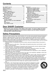
... ventilation can cause overheating and/or shorten the life of the product. do not place the product in the cabinet are followed. Contents Page Dear SHARP Customer 2 Safety Precautions 2 Supplied Accessories 4 Preparation 5 Example of Application 6 Listening with a Headphone 6 Names of Parts (Main Unit 7 Main Unit (...All warnings on an unstable cart, stand, tripod or table. Use a damp cloth to fall from the AC outlet before using this manual in a safe place-These safety and operating instructions must be kept in a safe place for ventilation. Do not cover or block these ...
... ventilation can cause overheating and/or shorten the life of the product. do not place the product in the cabinet are followed. Contents Page Dear SHARP Customer 2 Safety Precautions 2 Supplied Accessories 4 Preparation 5 Example of Application 6 Listening with a Headphone 6 Names of Parts (Main Unit 7 Main Unit (...All warnings on an unstable cart, stand, tripod or table. Use a damp cloth to fall from the AC outlet before using this manual in a safe place-These safety and operating instructions must be kept in a safe place for ventilation. Do not cover or block these ...
Operation Manual
Page 6
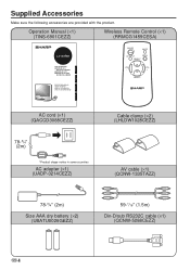
...;1) (TINS-6901CEZZ) Wireless Remote Control (×1) (RRMCG1459CESA) LC-20VM2 LCD AV MONITOR MONITEUR AV À CRISTAUX LIQUIDES MONITOR AV LCD MONITOR AV DE TELA DE CRISTAL LÍQUIDO OPERATION MANUAL MODE D'EMPLOI MANUAL DE MANEJO MANUAL DE OPERAÇÃO ESPAÑOL FRANÇAIS ENGLISH ON/OFF MUTE AV INPUT MENU SELECT VOL...
...;1) (TINS-6901CEZZ) Wireless Remote Control (×1) (RRMCG1459CESA) LC-20VM2 LCD AV MONITOR MONITEUR AV À CRISTAUX LIQUIDES MONITOR AV LCD MONITOR AV DE TELA DE CRISTAL LÍQUIDO OPERATION MANUAL MODE D'EMPLOI MANUAL DE MANEJO MANUAL DE OPERAÇÃO ESPAÑOL FRANÇAIS ENGLISH ON/OFF MUTE AV INPUT MENU SELECT VOL...
Operation Manual
Page 9
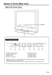
This manual describes button functions by referring to the buttons on the remote control. Names of Parts (Main Unit) Main Unit (Front View) Speakers Front Control section MENU HEAD PHONE − VOL + SELECT AV INPUT POWER POWER 1 2 3 4 5 6 78 1 Remote sensor window 2 HEAD PHONE jack 3 MENU button 4 VOL (+)/(-) buttons 5 SELECT buttons 6 AV INPUT button 7 POWER switch 8 POWER indicator * MENU button, VOL (+)/(-) buttons, SELECT buttons and AV INPUT button have the same function as those on the remote control. 7 US
This manual describes button functions by referring to the buttons on the remote control. Names of Parts (Main Unit) Main Unit (Front View) Speakers Front Control section MENU HEAD PHONE − VOL + SELECT AV INPUT POWER POWER 1 2 3 4 5 6 78 1 Remote sensor window 2 HEAD PHONE jack 3 MENU button 4 VOL (+)/(-) buttons 5 SELECT buttons 6 AV INPUT button 7 POWER switch 8 POWER indicator * MENU button, VOL (+)/(-) buttons, SELECT buttons and AV INPUT button have the same function as those on the remote control. 7 US
Operation Manual
Page 11
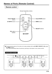
... INPUT MENU SELECT VOL - VOL + SELECT 9 US Names of the main unit is also provided with the AV INPUT, SELECT, VOL (+)/(-) and MENU buttons. * This manual describes button functions by referring to the buttons on the remote control. VOL + SELECT Sound MUTE button MENU button SELECT buttons s The front control section...
... INPUT MENU SELECT VOL - VOL + SELECT 9 US Names of the main unit is also provided with the AV INPUT, SELECT, VOL (+)/(-) and MENU buttons. * This manual describes button functions by referring to the buttons on the remote control. VOL + SELECT Sound MUTE button MENU button SELECT buttons s The front control section...
Operation Manual
Page 24
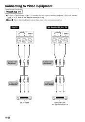
Via TV AUDIO R L VIDEO Via Satellite TV, Pay TV AUDIO R L VIDEO To VIDEO/AUDIO input terminal To VIDEO/AUDIO input terminal To VIDEO/AUDIO output terminal To VIDEO/AUDIO output terminal VCR, TV TUNER US 22 SATELLITE TUNER, SET TOP BOX(FOR PAY TV) Refer to the room antenna terminal. Note Refer to the manual how to connect these tuner to the diagram below for wiring. Connecting to Video Equipment Watching TV s To view a TV broadcast on the LCD monitor, the set-top box must be used with a TV tuner, satellite tuner or VCR.
Via TV AUDIO R L VIDEO Via Satellite TV, Pay TV AUDIO R L VIDEO To VIDEO/AUDIO input terminal To VIDEO/AUDIO input terminal To VIDEO/AUDIO output terminal To VIDEO/AUDIO output terminal VCR, TV TUNER US 22 SATELLITE TUNER, SET TOP BOX(FOR PAY TV) Refer to the room antenna terminal. Note Refer to the manual how to connect these tuner to the diagram below for wiring. Connecting to Video Equipment Watching TV s To view a TV broadcast on the LCD monitor, the set-top box must be used with a TV tuner, satellite tuner or VCR.
Operation Manual
Page 29
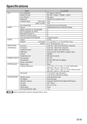
... Headphone jack DC operation AC operation Power consumption Exterior color Outside dimensions Net weight ACCESSORIES Remote control AC adapter Operation manual AC cord AV cable Cable clamp Din-D/sub RS232C cable LC-20VM2 20" (Approx. 500 mm) 921,600 = 640(H) × 3(RGB) × 480(V) Non-glare 400cd/m2 (at normally white) 120°...
... Headphone jack DC operation AC operation Power consumption Exterior color Outside dimensions Net weight ACCESSORIES Remote control AC adapter Operation manual AC cord AV cable Cable clamp Din-D/sub RS232C cable LC-20VM2 20" (Approx. 500 mm) 921,600 = 640(H) × 3(RGB) × 480(V) Non-glare 400cd/m2 (at normally white) 120°...


