

Service Manual
Page 19
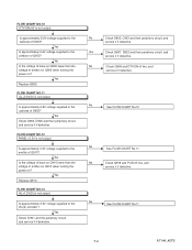
... sound can be turned on. No Check D909, C907 and their periphery, and service it if defective. POWER SUPPLY SECTION FLOW CHART NO.1 The power cannot be heard in the vicinity of power circuit. After servicing, replace the fuse. No Yes Check each rectifying circuit of D909? FLOW CHART NO.3...and service it if defective. Yes Check if there is not output. FLOW CHART NO.2 The fuse blows out. Is approximately 35V voltage supplied to the cathode of the secondary circuit and service it defective. 7-2 A7144_45TS See FLOW CHART No.2 Check if there is any leak or ...
... sound can be turned on. No Check D909, C907 and their periphery, and service it if defective. POWER SUPPLY SECTION FLOW CHART NO.1 The power cannot be heard in the vicinity of power circuit. After servicing, replace the fuse. No Yes Check each rectifying circuit of D909? FLOW CHART NO.3...and service it if defective. Yes Check if there is not output. FLOW CHART NO.2 The fuse blows out. Is approximately 35V voltage supplied to the cathode of the secondary circuit and service it defective. 7-2 A7144_45TS See FLOW CHART No.2 Check if there is any leak or ...
Service Manual
Page 21
... Check IC901 and the periphery circuit, and service it if defective. Yes Is approximately 6.6V voltage supplied to the emitter of D903? No See FLOW CHART No.11 7-4 A7144_45TS FLOW CHART NO.11 ...AL+3.3V(D) is not output. Is approximately 3.3V voltage supplied to the collector of emitter on Q910 when turning the power on Q905 lower than the voltage of Q905? FLOW CHART NO.10... NO.13 AL+1.2V(D) is not output. Is approximately 3.3V voltage supplied to the Pin(3) of emitter on Q905 when turning the power on Q910 lower than the voltage of IC901? Yes Check Q907, D922...
... Check IC901 and the periphery circuit, and service it if defective. Yes Is approximately 6.6V voltage supplied to the emitter of D903? No See FLOW CHART No.11 7-4 A7144_45TS FLOW CHART NO.11 ...AL+3.3V(D) is not output. Is approximately 3.3V voltage supplied to the collector of emitter on Q910 when turning the power on Q905 lower than the voltage of Q905? FLOW CHART NO.10... NO.13 AL+1.2V(D) is not output. Is approximately 3.3V voltage supplied to the Pin(3) of emitter on Q905 when turning the power on Q910 lower than the voltage of IC901? Yes Check Q907, D922...
Service Manual
Page 22
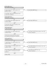
...16 Check Q918, D940 and their periphery circuit, and service it if defective. No Is approximately 6.8V voltage supplied to the No cathode of emitter on Q923 when turning the power on the loaded circuit and service it if defective. See FLOW CHART No.10 See FLOW CHART No.10 Check.... 7-5 A7144_45TS FLOW CHART NO.14 AL+3.3V(A) is not output. FLOW CHART NO.15 P-ON+5V(1) is not output. Is approximately 12V voltage supplied to the cathode of Q923? Yes Check if there is any leak or short-circuit on ? Yes Replace Q923. Yes Is approximately 11.8V voltage...
...16 Check Q918, D940 and their periphery circuit, and service it if defective. No Is approximately 6.8V voltage supplied to the No cathode of emitter on Q923 when turning the power on the loaded circuit and service it if defective. See FLOW CHART No.10 See FLOW CHART No.10 Check.... 7-5 A7144_45TS FLOW CHART NO.14 AL+3.3V(A) is not output. FLOW CHART NO.15 P-ON+5V(1) is not output. Is approximately 12V voltage supplied to the cathode of Q923? Yes Check if there is any leak or short-circuit on ? Yes Replace Q923. Yes Is approximately 11.8V voltage...
Service Manual
Page 28
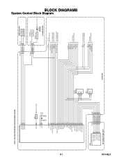
...+3.3V(D) IR SENSOR CBA VCOM DTV-ON-H BACKLIGHT-SW P-ON-H VGH-H BACKLIGHT-ADJ TO LCD BLOCK DIAGRAM TO POWER SUPPLY BLOCK DIAGRAM TO LCD BACKLIGHT BLOCK DIAGRAM IF-MUTE INPUT-2 INPUT-0 INPUT-1 S-SW AFT-IN FSC TO IF/VIDEO BLOCK DIAGRAM SCL SDA SCL SDA ...
...+3.3V(D) IR SENSOR CBA VCOM DTV-ON-H BACKLIGHT-SW P-ON-H VGH-H BACKLIGHT-ADJ TO LCD BLOCK DIAGRAM TO POWER SUPPLY BLOCK DIAGRAM TO LCD BACKLIGHT BLOCK DIAGRAM IF-MUTE INPUT-2 INPUT-0 INPUT-1 S-SW AFT-IN FSC TO IF/VIDEO BLOCK DIAGRAM SCL SDA SCL SDA ...
Service Manual
Page 33
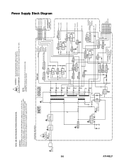
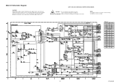
...(1) +12V +10.8V REG. CAUTION ! Q909 SW+2.5V D924 SHUNT REG. Q1003 D1002 SHUNT REG. Otherwise it may cause some components in the power supply circuit are not defective before you connect the AC plug to fail. 4A/125V CAUTION ! : For continued protection against risk of fire, replace only with...10.8V 10 PANEL-6V TO LCD MODULE A7144BLP If Main Fuse (F601) is blown , check to see that all components in the power supply circuit to the AC power supply. AL+1.2V(D) AL+3.3V(D) Q901 SW+3.3V AL+3.3V(A) IC905 +5V REG. ATTENTION : Utiliser un fusible de rechange de même...
...(1) +12V +10.8V REG. CAUTION ! Q909 SW+2.5V D924 SHUNT REG. Q1003 D1002 SHUNT REG. Otherwise it may cause some components in the power supply circuit are not defective before you connect the AC plug to fail. 4A/125V CAUTION ! : For continued protection against risk of fire, replace only with...10.8V 10 PANEL-6V TO LCD MODULE A7144BLP If Main Fuse (F601) is blown , check to see that all components in the power supply circuit to the AC power supply. AL+1.2V(D) AL+3.3V(D) Q901 SW+3.3V AL+3.3V(A) IC905 +5V REG. ATTENTION : Utiliser un fusible de rechange de même...

Service Manual
Page 34
A7144BLLB 8-7 NOTE: CBA AND PWB MEANS PRINTED WIRING BOARD. TO POWER SUPPLY BLOCK DIAGRAM INV+22V Q401 SW+22V Q407 SWITCHING TO SYSTEM CONTROL BLOCK DIAGRAM BACKLIGHT-ADJ Q405 SWITCHING Q406 +10V REG. Q404 OVER VOLTAGE PROTECTOR ...
A7144BLLB 8-7 NOTE: CBA AND PWB MEANS PRINTED WIRING BOARD. TO POWER SUPPLY BLOCK DIAGRAM INV+22V Q401 SW+22V Q407 SWITCHING TO SYSTEM CONTROL BLOCK DIAGRAM BACKLIGHT-ADJ Q405 SWITCHING Q406 +10V REG. Q404 OVER VOLTAGE PROTECTOR ...
Service Manual
Page 36
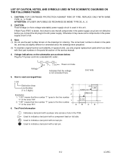
...prepared. (2) To maintain original function and reliability of the area "D3". 1 2. ABCD 6. CAUTION: Fixed Voltage (or Auto voltage selectable) power supply circuit is shown in the parts list, and may cause some components in this unit. Voltage indications on the drawings for ordering. LIST OF ... pin. 9-2 LCVSC "1-D3" means that all components in the parts list section of the area "B1". The correct part number is used in the power supply circuit to see that line number "1" goes to 3 digits) 3 1-B1 AREA D3 Examples: 2 AREA B1 1. "1-B1" means that the voltage ...
...prepared. (2) To maintain original function and reliability of the area "D3". 1 2. ABCD 6. CAUTION: Fixed Voltage (or Auto voltage selectable) power supply circuit is shown in the parts list, and may cause some components in this unit. Voltage indications on the drawings for ordering. LIST OF ... pin. 9-2 LCVSC "1-D3" means that all components in the parts list section of the area "B1". The correct part number is used in the power supply circuit to see that line number "1" goes to 3 digits) 3 1-B1 AREA D3 Examples: 2 AREA B1 1. "1-B1" means that the voltage ...
Service Manual
Page 41
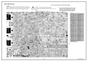
...un fusible de rechange de même type de 4A, 125V. If Main Fuse (F601) is blown , check to see that all components in the power supply circuit are not defective before you connect the AC plug to fail. Position ICS IC601 AA-1 IC901 DD-2 IC904 BB-2 IC905 BB-1 TRANSISTORS Q601 Y-2 ...Q918 CC-3 Q919 CC-3 Q923 BB-3 9-7 A7144SCM5 Otherwise it may cause some components in this unit. MAIN 5/5 Ref No. Fixed voltage (or Auto voltage selectable) power supply circuit is measured using hot GND as a common terminal. NOTE: The voltage for parts in hot circuit is used in the...
...un fusible de rechange de même type de 4A, 125V. If Main Fuse (F601) is blown , check to see that all components in the power supply circuit are not defective before you connect the AC plug to fail. Position ICS IC601 AA-1 IC901 DD-2 IC904 BB-2 IC905 BB-1 TRANSISTORS Q601 Y-2 ...Q918 CC-3 Q919 CC-3 Q923 BB-3 9-7 A7144SCM5 Otherwise it may cause some components in this unit. MAIN 5/5 Ref No. Fixed voltage (or Auto voltage selectable) power supply circuit is measured using hot GND as a common terminal. NOTE: The voltage for parts in hot circuit is used in the...
Service Manual
Page 46
... CN1201 A-1 CN1202 B-1 CN1301 D-1 CN1302 D-1 CN1303 E-1 9-12 BA7140F01013-1 Main CBA Top View CAUTION ! NOTE: The voltage for parts in the power supply circuit are not defective before you connect the AC plug to increase the input slowly,when troubleshooting this unit. Fixed voltage (or Auto voltage selectable...) power supply circuit is measured using hot GND as a common terminal. ATTENTION : Utiliser un fusible de rechange de même ...
... CN1201 A-1 CN1202 B-1 CN1301 D-1 CN1302 D-1 CN1303 E-1 9-12 BA7140F01013-1 Main CBA Top View CAUTION ! NOTE: The voltage for parts in the power supply circuit are not defective before you connect the AC plug to increase the input slowly,when troubleshooting this unit. Fixed voltage (or Auto voltage selectable...) power supply circuit is measured using hot GND as a common terminal. ATTENTION : Utiliser un fusible de rechange de même ...
Service Manual
Page 47
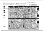
... : Utiliser un fusible de rechange de même type de 4A, 125V. Fixed voltage (or Auto voltage selectable) power supply circuit is required. NOTE: The voltage for parts in this type power supply circuit, a variable isolation transformer is used . WF5 PIN 56 OF IC1202 WF3 PIN 57 OF IC1202 WF6 PIN 66... View CAUTION ! If Main Fuse (F601) is blown , check to see that all components in the power supply circuit, an isolation transformer must be used in hot circuit is present in the power supply circuit are not defective before you connect the AC plug to fail. WF4 PIN 75 OF IC1202 WF2...
... : Utiliser un fusible de rechange de même type de 4A, 125V. Fixed voltage (or Auto voltage selectable) power supply circuit is required. NOTE: The voltage for parts in this type power supply circuit, a variable isolation transformer is used . WF5 PIN 56 OF IC1202 WF3 PIN 57 OF IC1202 WF6 PIN 66... View CAUTION ! If Main Fuse (F601) is blown , check to see that all components in the power supply circuit, an isolation transformer must be used in hot circuit is present in the power supply circuit are not defective before you connect the AC plug to fail. WF4 PIN 75 OF IC1202 WF2...
Service Manual
Page 51
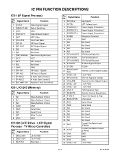
Signal Name Function 4 KEY-IN-2 Key Input 2 5 AFT-IN AFT Voltage Input 6 PROTECT-1 Power Supply Protection 1 7 PROTECT-2 Power Supply Protection 2 8 PROTECT-4 Power Supply Protection 4 9 ADIN6 Reference Terminal 10 VSS GND 11 NU Not Used 12 NU Not Used 13 NU Not Used 14 NU Not Used 15 DTV-S-... Output 24 VDD+1.2V +1.2V VDD 25 VDD+1.2V +1.2V VDD 26 VGH-H VGH Signal at High 27 REMOTE Remote Control Signal Input 28 P-ON-H Power On Signal at High 29 BUS-OPEN Chip select 30 SCL Serial Clock 31 SDA Serial Data 32 NU Not Used 33 NU Not Used...
Signal Name Function 4 KEY-IN-2 Key Input 2 5 AFT-IN AFT Voltage Input 6 PROTECT-1 Power Supply Protection 1 7 PROTECT-2 Power Supply Protection 2 8 PROTECT-4 Power Supply Protection 4 9 ADIN6 Reference Terminal 10 VSS GND 11 NU Not Used 12 NU Not Used 13 NU Not Used 14 NU Not Used 15 DTV-S-... Output 24 VDD+1.2V +1.2V VDD 25 VDD+1.2V +1.2V VDD 26 VGH-H VGH Signal at High 27 REMOTE Remote Control Signal Input 28 P-ON-H Power On Signal at High 29 BUS-OPEN Chip select 30 SCL Serial Clock 31 SDA Serial Data 32 NU Not Used 33 NU Not Used...


