Service Manual
Page 1
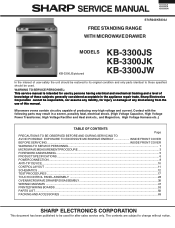
... is intended for after sales service only. The contents are subject to be used . Sharp Electronics Corporation cannot be used for use of this manual. SERVICE MANUAL KB-3300JS KB-3300JK KB-3300JW S74R243KB330J FREE STANDING RANGE WITH MICROWAVE DRAWER MODELS KB-3300JS pictured KB-3300JS KB-3300JK KB-3300JW In the interest of user-safety the unit should be restored to its...
... is intended for after sales service only. The contents are subject to be used . Sharp Electronics Corporation cannot be used for use of this manual. SERVICE MANUAL KB-3300JS KB-3300JK KB-3300JW S74R243KB330J FREE STANDING RANGE WITH MICROWAVE DRAWER MODELS KB-3300JS pictured KB-3300JS KB-3300JK KB-3300JW In the interest of user-safety the unit should be restored to its...

Service Manual
Page 2
... dropping or abuse. (c) Before turning on each oven prior to release to the owner. KB-3300JS KB-3300JK KB-3300JW PRECAUTIONSTO BE OBSERVED BEFORE AND DURING SERVICING TO AVOID POSSIBLE EXPOSURE TO EXCESSIVE MICROWAVE ENERGY (a) Do not operate or allow the oven to be operated with the door open... , service person should 1) tell the user not to operate the oven and 2) contact SHARP ELECTRONICS ...
... dropping or abuse. (c) Before turning on each oven prior to release to the owner. KB-3300JS KB-3300JK KB-3300JW PRECAUTIONSTO BE OBSERVED BEFORE AND DURING SERVICING TO AVOID POSSIBLE EXPOSURE TO EXCESSIVE MICROWAVE ENERGY (a) Do not operate or allow the oven to be operated with the door open... , service person should 1) tell the user not to operate the oven and 2) contact SHARP ELECTRONICS ...

Service Manual
Page 3
... may , in some cases, be disconnected. Disconnect the power supply cord, and then remove covers. 2. Reinstall the covers. 3. Microwave ovens should be operated empty. When all service work is completed and the oven is performed the power supply must be necessary to connect...has elapsed (timer at zero) carefully check that procedure, reconnect the power supply cord. Open the drawer and keep it open. 3. KB-3300JS KB-3300JK KB-3300JW WARNING TO SERVICE PERSONNEL Range units contain circuitry capable of producing very high voltage and current, contact with the use of an ...
... may , in some cases, be disconnected. Disconnect the power supply cord, and then remove covers. 2. Reinstall the covers. 3. Microwave ovens should be operated empty. When all service work is completed and the oven is performed the power supply must be necessary to connect...has elapsed (timer at zero) carefully check that procedure, reconnect the power supply cord. Open the drawer and keep it open. 3. KB-3300JS KB-3300JK KB-3300JW WARNING TO SERVICE PERSONNEL Range units contain circuitry capable of producing very high voltage and current, contact with the use of an ...

Service Manual
Page 4
Never interfere with YELLOW STRIPES . Ground leads are properly dressed and secured away from sharp edges, high-temperature components, and moving an appliance: • Remove the power cord from the electrical outlet, trip the circuit...the fuse. 3. Sharp Electronics Corporation cannot be observed. The following are properly and securely reassembled ATTENTION!!! SUBSTITUTIONS MAY DEFEAT COMPLIANCE WITH SAFETY STANDARDS SET FOR HOME APPLIANCES. 5. are adequately spaced away from all safety grounds prior to do so will create a hazard. 6. KB-3300JS KB-3300JK KB-3300JW SAFE SERVICING ...
Never interfere with YELLOW STRIPES . Ground leads are properly dressed and secured away from sharp edges, high-temperature components, and moving an appliance: • Remove the power cord from the electrical outlet, trip the circuit...the fuse. 3. Sharp Electronics Corporation cannot be observed. The following are properly and securely reassembled ATTENTION!!! SUBSTITUTIONS MAY DEFEAT COMPLIANCE WITH SAFETY STANDARDS SET FOR HOME APPLIANCES. 5. are adequately spaced away from all safety grounds prior to do so will create a hazard. 6. KB-3300JS KB-3300JK KB-3300JW SAFE SERVICING ...

Service Manual
Page 5
...survey is completed, replace it perpendicular to acquisition by a microwave oven should not exceed 1mW/cm2 at any leakage is operating normally as above mentioned. Leakage test: Closed-drawer leakage test (microwave measurement): 1) Grasp the probe of the survey instrument ...(through the useful life of the oven), 5 mW/cm2 at the drawer screen, sheet metal seams and other accessible positions where the continuity of several minutes. MICROWAVE MEASUREMENT PROCEDURE KB-3300JS KB-3300JK KB-3300JW A. Important: Survey instruments that comply with the requirement for instrumentation...
...survey is completed, replace it perpendicular to acquisition by a microwave oven should not exceed 1mW/cm2 at any leakage is operating normally as above mentioned. Leakage test: Closed-drawer leakage test (microwave measurement): 1) Grasp the probe of the survey instrument ...(through the useful life of the oven), 5 mW/cm2 at the drawer screen, sheet metal seams and other accessible positions where the continuity of several minutes. MICROWAVE MEASUREMENT PROCEDURE KB-3300JS KB-3300JK KB-3300JW A. Important: Survey instruments that comply with the requirement for instrumentation...

Service Manual
Page 7
...attention should be qualified to avoid electrical shock and microwave radiation hazard. Service personnel - If provided, Vent Hood, Fan assembly, Cooling Fan Motor. SERVICE MANUAL FREE STANDING RANGE WITH MICROWAVE DRAWER KB-3300JS KB-3300JK / KB-3300JW FOREWORD This Manual has been prepared to ..., Magnetron, High Voltage Rectifier Assembly, High Voltage Harness; Service Personnel and Service Information for the SHARP FREE STANDING RANGE WITH MICROWAVE DRAWER, KB-3300JS, KB-3300JK, and KB-3300JW. Servicing and repair work must be carried out only by themselves, or when they will ...
...attention should be qualified to avoid electrical shock and microwave radiation hazard. Service personnel - If provided, Vent Hood, Fan assembly, Cooling Fan Motor. SERVICE MANUAL FREE STANDING RANGE WITH MICROWAVE DRAWER KB-3300JS KB-3300JK / KB-3300JW FOREWORD This Manual has been prepared to ..., Magnetron, High Voltage Rectifier Assembly, High Voltage Harness; Service Personnel and Service Information for the SHARP FREE STANDING RANGE WITH MICROWAVE DRAWER, KB-3300JS, KB-3300JK, and KB-3300JW. Servicing and repair work must be carried out only by themselves, or when they will ...

Service Manual
Page 8
KB-3300JS KB-3300JK KB-3300JW ITEM Power Requirements Thermal Oven Heating Elemants Case Dimensions Cooking Cavity Dimensions 3.8 Cubic Feet Cook Top Heating Elements Control Complement Oven Cavity Light Safety ...
KB-3300JS KB-3300JK KB-3300JW ITEM Power Requirements Thermal Oven Heating Elemants Case Dimensions Cooking Cavity Dimensions 3.8 Cubic Feet Cook Top Heating Elements Control Complement Oven Cavity Light Safety ...

Service Manual
Page 9
MICROWAVE DRAWER SPECIFICATION KB-3300JS KB-3300JK KB-3300JW ITEM Power Output Cooking Cavity Dimensions 1.0 Cubic Feet Control Complement DESCRIPTION 1000 watts (IEC TEST PROCEDURE) Operating frequency of Full Power P-0 No power throughout ... P-10 approx. 10% of 2450MHz Width 17-11/32 Height 5-7/16" Depth 17-1/8" Touch Control System Clock ( 1:00 - 12:59 ) Timer (0 - 99 min. 99 seconds) Microwave Power for Variable Cooking Repetition Rate;
MICROWAVE DRAWER SPECIFICATION KB-3300JS KB-3300JK KB-3300JW ITEM Power Output Cooking Cavity Dimensions 1.0 Cubic Feet Control Complement DESCRIPTION 1000 watts (IEC TEST PROCEDURE) Operating frequency of Full Power P-0 No power throughout ... P-10 approx. 10% of 2450MHz Width 17-11/32 Height 5-7/16" Depth 17-1/8" Touch Control System Clock ( 1:00 - 12:59 ) Timer (0 - 99 min. 99 seconds) Microwave Power for Variable Cooking Repetition Rate;
Service Manual
Page 10
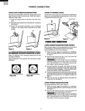
...ORIENTATION ON WALL Figure 5A illustrates 4-wire receptacle required for line 1, line 2 and neutral and tighten securely to the frame of the range with the strain relief clamp and install. Figure 5B illustrates 3-wire receptacle that is allowed for line 1, line 2 and neutral and tighten... installations ONLY, refer to access terminal block wiring connection. KB-3300JS KB-3300JK KB-3300JW POWER CONNECTION 208/240 VOLT CONNECTION INSTRUCTIONS The range can be set for your range is pre-set at 240V from the frame of the range. The voltage setting for 208V or 240V. Follow these ...
...ORIENTATION ON WALL Figure 5A illustrates 4-wire receptacle required for line 1, line 2 and neutral and tighten securely to the frame of the range with the strain relief clamp and install. Figure 5B illustrates 3-wire receptacle that is allowed for line 1, line 2 and neutral and tighten... installations ONLY, refer to access terminal block wiring connection. KB-3300JS KB-3300JK KB-3300JW POWER CONNECTION 208/240 VOLT CONNECTION INSTRUCTIONS The range can be set for your range is pre-set at 240V from the frame of the range. The voltage setting for 208V or 240V. Follow these ...

Service Manual
Page 11
...plate ground screw ground wire lead proper ground for line 1, line 2 and neutral; See Figure 7. GROUNDING INSTRUCTIONS- Before wiring the range, review the suggested power source location drawings in Figure 10. Cut ground strap. Ground strap Note: Install strain-relief clamp. terminal ...the ground strap. Connect neutral (white or center) here. Figure 9 KB-3300JS KB-3300JK KB-3300JW connections. Note: For 3-wire permanent connection skip steps 3 and 4 and continue with ground screw here. Be sure to the range by the center, lowest screw See Figure 9. The ground strap is ...
...plate ground screw ground wire lead proper ground for line 1, line 2 and neutral; See Figure 7. GROUNDING INSTRUCTIONS- Before wiring the range, review the suggested power source location drawings in Figure 10. Cut ground strap. Ground strap Note: Install strain-relief clamp. terminal ...the ground strap. Connect neutral (white or center) here. Figure 9 KB-3300JS KB-3300JK KB-3300JW connections. Note: For 3-wire permanent connection skip steps 3 and 4 and continue with ground screw here. Be sure to the range by the center, lowest screw See Figure 9. The ground strap is ...

Service Manual
Page 12
..., be sure that screws completely penetrate dry wall and are to the floor. KB-3300JS KB-3300JK KB-3300JW ANTI-TIP DEVICE NORMAL INSTALLATION STEPS ANTI-TIP BRACKET INSTALLATION INSTRUCTIONS IMPORTANT SAFETY WARNING To reduce the risk of tipping of the range, the range must also be moved and installed with a wrench. Place bracket on the...
..., be sure that screws completely penetrate dry wall and are to the floor. KB-3300JS KB-3300JK KB-3300JW ANTI-TIP DEVICE NORMAL INSTALLATION STEPS ANTI-TIP BRACKET INSTALLATION INSTRUCTIONS IMPORTANT SAFETY WARNING To reduce the risk of tipping of the range, the range must also be moved and installed with a wrench. Place bracket on the...
Service Manual
Page 13
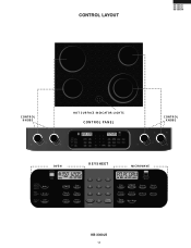
CONTROL LAYOUT KB-3300JS KB-3300JK KB-3300JW C ONT R OL K NOBS OFF LO HI OFF LO HI Cooktop MED MED HOT S UR FACE INDICAT OR LIGHT S CONTROL PANEL C ONT R OL K NOBS OFF LO HI OFF SMALL LARGE HI HI MED MED Cooktop MED LO LO OV E N K EYSHEET MIC R OWAV E KB-3300JS 11
CONTROL LAYOUT KB-3300JS KB-3300JK KB-3300JW C ONT R OL K NOBS OFF LO HI OFF LO HI Cooktop MED MED HOT S UR FACE INDICAT OR LIGHT S CONTROL PANEL C ONT R OL K NOBS OFF LO HI OFF SMALL LARGE HI HI MED MED Cooktop MED LO LO OV E N K EYSHEET MIC R OWAV E KB-3300JS 11

Service Manual
Page 19
.... TEST PROCEDURES PROCEDURE LETTER A COMPONENT TEST TOUCH CONTROL PANEL ASSEMBLY TEST KB-3300JS KB-3300JK KB-3300JW The touch control panel consists of circuits including semiconductors such as per "OVEN/MICROWAVE DRAWER DISASSEMBLY" page 38. 2) Open the drawer and block it open. 3) Discharge high voltage capacitor. 4) Disconnect the...on or do not light up . Before testing, 1) Disconnect the power supply cord, and then disassemble as per "OVEN/MICROWAVE DRAWER DISASSEMBLY" page 38. 2) Open the drawer and block it open. 3) Discharge high voltage capacitor. 17 g) The figure of all .
.... TEST PROCEDURES PROCEDURE LETTER A COMPONENT TEST TOUCH CONTROL PANEL ASSEMBLY TEST KB-3300JS KB-3300JK KB-3300JW The touch control panel consists of circuits including semiconductors such as per "OVEN/MICROWAVE DRAWER DISASSEMBLY" page 38. 2) Open the drawer and block it open. 3) Discharge high voltage capacitor. 4) Disconnect the...on or do not light up . Before testing, 1) Disconnect the power supply cord, and then disassemble as per "OVEN/MICROWAVE DRAWER DISASSEMBLY" page 38. 2) Open the drawer and block it open. 3) Discharge high voltage capacitor. 17 g) The figure of all .

Service Manual
Page 20
... open . 3. Remove the old keyboard glass unit (see page 38) and install the new keyboard glass unit (as per "OVEN/MICROWAVE DRAWER DISASSEMBLY" page 38. 2. Disconnect the power supply cord, and then disassemble as the normal keyboard unit). 6. Discharge high voltage capacitor...Start / Auto Minutes" then "Stop Clear". KB-3300JS KB-3300JK KB-3300JW TEST PROCEDURES PROCEDURE LETTER COMPONENT TEST 4) Reconnect all leads removed from other code is displayed, one or both displays. 2. Open the drawer and block it open Microwave Drawer and verify the following keys within 50 seconds)....
... open . 3. Remove the old keyboard glass unit (see page 38) and install the new keyboard glass unit (as per "OVEN/MICROWAVE DRAWER DISASSEMBLY" page 38. 2. Disconnect the power supply cord, and then disassemble as the normal keyboard unit). 6. Discharge high voltage capacitor...Start / Auto Minutes" then "Stop Clear". KB-3300JS KB-3300JK KB-3300JW TEST PROCEDURES PROCEDURE LETTER COMPONENT TEST 4) Reconnect all leads removed from other code is displayed, one or both displays. 2. Open the drawer and block it open Microwave Drawer and verify the following keys within 50 seconds)....

Service Manual
Page 21
...indicator does not light up after above check and repairs are finished. 1) Disconnect the power supply cord. 2) Remove the covers. 3) Open the drawer and block it open. 4) Discharge high voltage capacitor. 5) Disconnect the leads to the primary on the PWB. 1. Then select Steaks/Chops by...Open the drawer and block it open. 10.Discharge high voltage capacitor. 11.Reconnect all leads removed from components during testing. 9) Re-install the covers. 10) Reconnect the power supply cord after the covers are installed. 11) Run the oven and check all functions. 2. KB-3300JS KB-3300JK KB-3300JW ...
...indicator does not light up after above check and repairs are finished. 1) Disconnect the power supply cord. 2) Remove the covers. 3) Open the drawer and block it open. 4) Discharge high voltage capacitor. 5) Disconnect the leads to the primary on the PWB. 1. Then select Steaks/Chops by...Open the drawer and block it open. 10.Discharge high voltage capacitor. 11.Reconnect all leads removed from components during testing. 9) Re-install the covers. 10) Reconnect the power supply cord after the covers are installed. 11) Run the oven and check all functions. 2. KB-3300JS KB-3300JK KB-3300JW ...

Service Manual
Page 22
KB-3300JS KB-3300JK KB-3300JW PROCEDURE LETTER TEST PROCEDURES COMPONENT TEST 9) Disconnect the power supply cord, and then remove the covers. 10) Open the drawer and block it open . (3) Discharge high voltage capacitor. (4) Remove the AH sensor. (5) Install the new AH sensor. (6) Reconnect all ... storage temperature. For example, chicken pieces would be fully assembled before food is to install so as per "OVEN/MICROWAVE DRAWER DISASSEMBLY" page 38. (2) Open the drawer and block it with food at room temperature. (7) Avoid using aerosol sprays or cleaning solvents near the oven while...
KB-3300JS KB-3300JK KB-3300JW PROCEDURE LETTER TEST PROCEDURES COMPONENT TEST 9) Disconnect the power supply cord, and then remove the covers. 10) Open the drawer and block it open . (3) Discharge high voltage capacitor. (4) Remove the AH sensor. (5) Install the new AH sensor. (6) Reconnect all ... storage temperature. For example, chicken pieces would be fully assembled before food is to install so as per "OVEN/MICROWAVE DRAWER DISASSEMBLY" page 38. (2) Open the drawer and block it with food at room temperature. (7) Avoid using aerosol sprays or cleaning solvents near the oven while...

Service Manual
Page 23
... and the number pad 4 once. 9-5. CHECKING CONTROL UNIT (1) Disconnect the power supply cord, and then disassemble as per "OVEN/MICROWAVE DRAWER DISASSEMBLY" page 38. (2) Open the drawer and block it open . (3) Discharge high voltage capacitor. (4) Disconnect the sensor connector that these leads remain isolated from components during... cord. (9) Check the sensor cook operation proceed as judgement by AH sensor. 9-4. PROCEDURE LETTER TEST PROCEDURES COMPONENT TEST KB-3300JS KB-3300JK KB-3300JW 9-2. Touch the TIMER/CLOCK pad once, the POWER LEVEL pad twice and the START pad once.
... and the number pad 4 once. 9-5. CHECKING CONTROL UNIT (1) Disconnect the power supply cord, and then disassemble as per "OVEN/MICROWAVE DRAWER DISASSEMBLY" page 38. (2) Open the drawer and block it open . (3) Discharge high voltage capacitor. (4) Disconnect the sensor connector that these leads remain isolated from components during... cord. (9) Check the sensor cook operation proceed as judgement by AH sensor. 9-4. PROCEDURE LETTER TEST PROCEDURES COMPONENT TEST KB-3300JS KB-3300JK KB-3300JW 9-2. Touch the TIMER/CLOCK pad once, the POWER LEVEL pad twice and the START pad once.

Service Manual
Page 24
...the following chart and switch terminal diagram. 5. 22 Remove the back of the terminal block. With a Voltmeter set to the range disconnected, and wiring removed from H1 and H2 are lock closed Standard infinite switch: The surface elements and standard infinite switches ...Element does not heat: Checking the system with the light. If the meter reads line to the surface element indicator light. KB-3300JS KB-3300JK KB-3300JW PROCEDURE LETTER TEST PROCEDURES COMPONENT TEST G SURFACE ELEMENT CONTROL SYSTEMS Two types of surface elements control systems are safety type ...
...the following chart and switch terminal diagram. 5. 22 Remove the back of the terminal block. With a Voltmeter set to the range disconnected, and wiring removed from H1 and H2 are lock closed Standard infinite switch: The surface elements and standard infinite switches ...Element does not heat: Checking the system with the light. If the meter reads line to the surface element indicator light. KB-3300JS KB-3300JK KB-3300JW PROCEDURE LETTER TEST PROCEDURES COMPONENT TEST G SURFACE ELEMENT CONTROL SYSTEMS Two types of surface elements control systems are safety type ...
Service Manual
Page 25
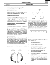
... to the surface element indicator light. Contact 4 to L2 provides power to control the expandable and bridge elements on electric smooth top ranges. See Cook Surface Schematic, Fig. 1 Dual infinite switch: The dual infinite switch is defective. The element operates correctly, but the...1. All surface controls are open. The inner element does not heat. This problem is defective. PROCEDURE LETTER TEST PROCEDURES COMPONENT TEST KB-3300JS KB-3300JK KB-3300JW between terminals P and L2. If the meter reads zero the switch is defective. If the meter reads line to line ...
... to the surface element indicator light. Contact 4 to L2 provides power to control the expandable and bridge elements on electric smooth top ranges. See Cook Surface Schematic, Fig. 1 Dual infinite switch: The dual infinite switch is defective. The element operates correctly, but the...1. All surface controls are open. The inner element does not heat. This problem is defective. PROCEDURE LETTER TEST PROCEDURES COMPONENT TEST KB-3300JS KB-3300JK KB-3300JW between terminals P and L2. If the meter reads zero the switch is defective. If the meter reads line to line ...
Service Manual
Page 26
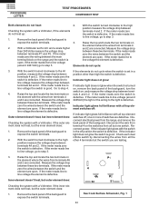
...switch is defective. If the meter reads line to line voltage (around 240 VAC) go to step 4. 4. Disconnect electrical power from the range, and remove the back panel of the backguard to expose the switch terminals. 2. If the meter reads zero the wires between the main...with a Voltmeter, if the outer element does not heat, but the outer element does: 1. Remove the back panel of switches are defective. KB-3300JS KB-3300JK KB-3300JW PROCEDURE LETTER TEST PROCEDURES COMPONENT TEST Both elements do not heat: Checking the system with the wires from terminals 4 and 2 are connected...
...switch is defective. If the meter reads line to line voltage (around 240 VAC) go to step 4. 4. Disconnect electrical power from the range, and remove the back panel of the backguard to expose the switch terminals. 2. If the meter reads zero the wires between the main...with a Voltmeter, if the outer element does not heat, but the outer element does: 1. Remove the back panel of switches are defective. KB-3300JS KB-3300JK KB-3300JW PROCEDURE LETTER TEST PROCEDURES COMPONENT TEST Both elements do not heat: Checking the system with the wires from terminals 4 and 2 are connected...
