DT-500 Operation Manual
Page 12
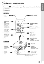
ENTER button 41 For setting items selected or adjusted on and putting the projector into standby mode. Projector Top View Power indicator 28, 52 28, 52 Lamp indicator STANDBY/ON 28 button For turning the power on the menu. RESIZE button 36 For ... adjustment and setting screens. 41 Adjustment buttons (P/R/O/Q) For selecting menu items. 51 Intake vent 30 Zoom ring For enlarging/ reducing the picture. 15 Remote control sensor (front) Push both sides of the lens cap to the main pages in this operation manual where the topic is explained.
ENTER button 41 For setting items selected or adjusted on and putting the projector into standby mode. Projector Top View Power indicator 28, 52 28, 52 Lamp indicator STANDBY/ON 28 button For turning the power on the menu. RESIZE button 36 For ... adjustment and setting screens. 41 Adjustment buttons (P/R/O/Q) For selecting menu items. 51 Intake vent 30 Zoom ring For enlarging/ reducing the picture. 15 Remote control sensor (front) Push both sides of the lens cap to the main pages in this operation manual where the topic is explained.

DT-500 Operation Manual
Page 13
... 6 terminal Connecting video equipment with hard disc, etc.). INPUT 3 terminal 2 Connecting video equipment with hard disc, etc.). Rear adjustment 31 foot Terminals 15 Remote control sensor (rear) 13 Kensington Security Standard connector 65 4 1 23 Terminal Description INPUT 1, 2 terminal 1 Connecting video equipment with component output terminal (DVD player, DTV decoder, DVD recorder...
... 6 terminal Connecting video equipment with hard disc, etc.). INPUT 3 terminal 2 Connecting video equipment with hard disc, etc.). Rear adjustment 31 foot Terminals 15 Remote control sensor (rear) 13 Kensington Security Standard connector 65 4 1 23 Terminal Description INPUT 1, 2 terminal 1 Connecting video equipment with component output terminal (DVD player, DTV decoder, DVD recorder...

DT-500 Operation Manual
Page 16
...8226; Ensure that you do not drop, expose to control the projector within the ranges shown in the illustration. Remote control sensor (front) 30° Remote control signal transmitters 30° 23n (7 m) Remote control Remote control sensor (rear) 23n (7 m) 30° Remote control signal transmitters... 30° Remote control Note • The signal from the fluorescent lamp. 15 In this case, move the projector away from the remote control can be reflected off ...
...8226; Ensure that you do not drop, expose to control the projector within the ranges shown in the illustration. Remote control sensor (front) 30° Remote control signal transmitters 30° 23n (7 m) Remote control Remote control sensor (rear) 23n (7 m) 30° Remote control signal transmitters... 30° Remote control Note • The signal from the fluorescent lamp. 15 In this case, move the projector away from the remote control can be reflected off ...
DT-500 Operation Manual
Page 61
... on the projector's remote control sensor, place the projector where it in the best picture quality. Make sure the batteries are incorrectly set. The image sometimes • Cables incorrectly connected to obtain product literature, accessories, supplies or customer assistance, please call 1-800-BE-SHARP (1-800-2374277) or visit SHARP's website (http://www.sharpusa.com). 60...
... on the projector's remote control sensor, place the projector where it in the best picture quality. Make sure the batteries are incorrectly set. The image sometimes • Cables incorrectly connected to obtain product literature, accessories, supplies or customer assistance, please call 1-800-BE-SHARP (1-800-2374277) or visit SHARP's website (http://www.sharpusa.com). 60...

DT-500 Operation Manual
Page 64
button 48 RS-232C Setting 50 Saturation 44 Sharp 43 SIDE BAR 36, 37 Special Modes 46 STANDBY button 29 STANDBY/ON button 28, 29 STANDBY Mode 50 STRETCH 36, 37 Subtitle 47 Supplied ... Distance ....... 20 Power cord 28 PRJ Mode 19, 49 Progressive 44 R-03 batteries 14 Rear adjustment foot 31 Red 43 Remote control 13 Remote control sensor 15 Replacing the lamp 54, 55 Resize 36, 37 RESIZE button 36 RETURN button 41 RGB/COMP.
button 48 RS-232C Setting 50 Saturation 44 Sharp 43 SIDE BAR 36, 37 Special Modes 46 STANDBY button 29 STANDBY/ON button 28, 29 STANDBY Mode 50 STRETCH 36, 37 Subtitle 47 Supplied ... Distance ....... 20 Power cord 28 PRJ Mode 19, 49 Progressive 44 R-03 batteries 14 Rear adjustment foot 31 Red 43 Remote control 13 Remote control sensor 15 Replacing the lamp 54, 55 Resize 36, 37 RESIZE button 36 RETURN button 41 RGB/COMP.
