Service Manual
Page 1
19C140 SERVICE MANUAL COLOR TELEVISION Chassis No. SHARP CORPORATION This document has been published to change without notice. CONTENTS Page » ELECTRICAL SPECIFICATIONS ...1 » IMPORTANT SERVICE SAFETY PRECAUTION 2 » LOCATION OF USER'S CONTROL ...4 » INSTALLATION AND SERVICE INSTRUCTIONS 5 » CHASSIS LAYOUT ...10 » BLOCK DIAGRAM ...11 » SCHEMATIC DIAGRAMS ...12 » PRINTED WIRING BOARD ASSEMBLIES 15 » REPLACEMENT PARTS LIST ...18 » PACKING OF THE SET ...23 ELECTRICAL SPECIFICATIONS POWER INPUT 120 V AC 60 Hz POWER ...
19C140 SERVICE MANUAL COLOR TELEVISION Chassis No. SHARP CORPORATION This document has been published to change without notice. CONTENTS Page » ELECTRICAL SPECIFICATIONS ...1 » IMPORTANT SERVICE SAFETY PRECAUTION 2 » LOCATION OF USER'S CONTROL ...4 » INSTALLATION AND SERVICE INSTRUCTIONS 5 » CHASSIS LAYOUT ...10 » BLOCK DIAGRAM ...11 » SCHEMATIC DIAGRAMS ...12 » PRINTED WIRING BOARD ASSEMBLIES 15 » REPLACEMENT PARTS LIST ...18 » PACKING OF THE SET ...23 ELECTRICAL SPECIFICATIONS POWER INPUT 120 V AC 60 Hz POWER ...
Service Manual
Page 2
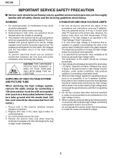
... the "High Voltage Check" instructions. Every time a color chassis is as a test probe) between the line cord and power receptacle, when servicing this receiver has two ground systems which follow: WARNING X-RADIATION AND HIGH VOLTAGE LIMITS 1. SERVICING OF HIGH VOLTAGE SYSTEM AND PICTURE TUBE When servicing the high voltage system, remove the static charge by qualified service technicians who are thoroughly familiar...
... the "High Voltage Check" instructions. Every time a color chassis is as a test probe) between the line cord and power receptacle, when servicing this receiver has two ground systems which follow: WARNING X-RADIATION AND HIGH VOLTAGE LIMITS 1. SERVICING OF HIGH VOLTAGE SYSTEM AND PICTURE TUBE When servicing the high voltage system, remove the static charge by qualified service technicians who are thoroughly familiar...
Service Manual
Page 3
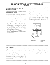
...Using two clip leads, connect a 1.5k ohm, 10 watt resistor paralleled by "å" and shaded areas in this service manual, may rated for higher voltage, wattage and etc. Replacement parts which do not have special safety-related characteristics. electrical components having a return to the chassis (antenna, metal cabinet, screw heads, knobs and control...repeated with the AC ine cord plug connection reversed. (If necessary, a nonpolarized adapter plug must not exceed 0.5 milliamp. Inspect all protective devices such as the factory recommended necessarily increased by them ...
...Using two clip leads, connect a 1.5k ohm, 10 watt resistor paralleled by "å" and shaded areas in this service manual, may rated for higher voltage, wattage and etc. Replacement parts which do not have special safety-related characteristics. electrical components having a return to the chassis (antenna, metal cabinet, screw heads, knobs and control...repeated with the AC ine cord plug connection reversed. (If necessary, a nonpolarized adapter plug must not exceed 0.5 milliamp. Inspect all protective devices such as the factory recommended necessarily increased by them ...
Service Manual
Page 4
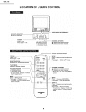
19C140 LOCATION OF USER'S CONTROL 4
19C140 LOCATION OF USER'S CONTROL 4
Service Manual
Page 5
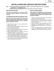
... 28.9V DC at least 15 minutes. 19C140 INSTALLATION AND SERVICE INSTRUCTIONS Note: (1) When performing any adjustments to resistor controls and transformers use non-metallic screwdrivers or TV alignment tools. (2) Before performing adjustments, the TV set is protected by using a variac transformer for accurate input voltage. 2) Allow for warm up and adjust all customer controls for malfunctioning components. Connect an accurate high voltage meter between TP651 and...
... 28.9V DC at least 15 minutes. 19C140 INSTALLATION AND SERVICE INSTRUCTIONS Note: (1) When performing any adjustments to resistor controls and transformers use non-metallic screwdrivers or TV alignment tools. (2) Before performing adjustments, the TV set is protected by using a variac transformer for accurate input voltage. 2) Allow for warm up and adjust all customer controls for malfunctioning components. Connect an accurate high voltage meter between TP651 and...
Service Manual
Page 6
... AC cord into the service mode, check that customer adjustments are required. 1. The service adjustment number will vary in their proper (reset) position. 2. Note: There are in increments of this series such as focus and master screen voltage. Use the reset function in the video adjustment menu to ensure customer controls are still a few analog adjustments in the normal mode. To exit the service mode, turn the television off by the D/A converter circuit.
... AC cord into the service mode, check that customer adjustments are required. 1. The service adjustment number will vary in their proper (reset) position. 2. Note: There are in increments of this series such as focus and master screen voltage. Use the reset function in the video adjustment menu to ensure customer controls are still a few analog adjustments in the normal mode. To exit the service mode, turn the television off by the D/A converter circuit.

Service Manual
Page 7
A Holding down both the CH-up /down buttons on the TV set at service mode for more than 2 seconds will automatically write the above initial values into IC2101. IC201 X The adjustment is stored in the service mode for characteristics of parts including IC201. 19C140 SERVICE NUMBER ADJUSTMENT ITEM S01 PICTURE S02 TINT S03 COLOR S04 BRIGHTNESS S05 SHARPNESS S06 VERTICAL PHASE S07 HORIZONTAL PHASE S08 RF-AGC...
A Holding down both the CH-up /down buttons on the TV set at service mode for more than 2 seconds will automatically write the above initial values into IC2101. IC201 X The adjustment is stored in the service mode for characteristics of parts including IC201. 19C140 SERVICE NUMBER ADJUSTMENT ITEM S01 PICTURE S02 TINT S03 COLOR S04 BRIGHTNESS S05 SHARPNESS S06 VERTICAL PHASE S07 HORIZONTAL PHASE S08 RF-AGC...
Service Manual
Page 8
... to come out of the service mode to select another channel to be provided. Sub-Picture Adjustment 1. Make sure the customer picture control is set to center position . 3. Make sure the customer color control is set to maximum. 3. Adjustment is barely seen. 7. RF AGC Adjustment 1. Adjust the service adjustments "S11" red, "S12" green and "S13" blue to "00" (minimum color)(Record original data code under adjustment "S03" before changing). Remove digital voltmeter, and reset the master screen control to...
... to come out of the service mode to select another channel to be provided. Sub-Picture Adjustment 1. Make sure the customer picture control is set to center position . 3. Make sure the customer color control is set to maximum. 3. Adjustment is barely seen. 7. RF AGC Adjustment 1. Adjust the service adjustments "S11" red, "S12" green and "S13" blue to "00" (minimum color)(Record original data code under adjustment "S03" before changing). Remove digital voltmeter, and reset the master screen control to...
Service Manual
Page 9
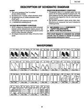
... 4.6 0.7 33 39.0 1160 220 150 133 220 1.7 0.7 1.4 105 95 105 9 This circuit diagram is omitted. (K=kΩ=1000Ω, M=MΩ) 2. The wave shapes at 120V AC and all controls set for normal picture unless otherwise indicated. 2. The unit of the picture tube depend on a standard gated color bar signal, the tint setting adjusted for product improvement without prior notice. indicates line isolated ground.
... 4.6 0.7 33 39.0 1160 220 150 133 220 1.7 0.7 1.4 105 95 105 9 This circuit diagram is omitted. (K=kΩ=1000Ω, M=MΩ) 2. The wave shapes at 120V AC and all controls set for normal picture unless otherwise indicated. 2. The unit of the picture tube depend on a standard gated color bar signal, the tint setting adjusted for product improvement without prior notice. indicates line isolated ground.
Service Manual
Page 15
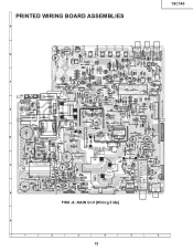
PRINTED WIRING BOARD ASSEMBLIES H 19C140 G F E D C B P WB -A: MAIN Unit (Wiring S ide) A 1 2 3 4 5 6 15
PRINTED WIRING BOARD ASSEMBLIES H 19C140 G F E D C B P WB -A: MAIN Unit (Wiring S ide) A 1 2 3 4 5 6 15
Service Manual
Page 18
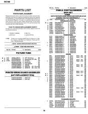
... in the Replacement Parts Lists and Schematic Diagrams. The use of SHARP Parts Distributor, Please call TollFree; 1-800-BE-SHARP « MARK: SPARE PARTS-DELIVERY SECTION p MARK: X-RAY RELATED PARTS Ref. DUNTKA359WEW0 - MODEL NUMBER 3. CRT Unit - PART NO. 2. Ref. No. Part No. « Description Code U pU U U U U U U U p U p U U U U U PWB-A: DUNTKA358WEX9 MAIN UNIT TUNER NOTE:THE PARTS HERE SHOWN ARE SUPPLIED AS AN ASSEMBLY BUT NOT INDEPENDETLY TU51 VTUVT1T5UF214 X TUNER AP INTEGRATED CIRCUITS IC201 RH...
... in the Replacement Parts Lists and Schematic Diagrams. The use of SHARP Parts Distributor, Please call TollFree; 1-800-BE-SHARP « MARK: SPARE PARTS-DELIVERY SECTION p MARK: X-RAY RELATED PARTS Ref. DUNTKA359WEW0 - MODEL NUMBER 3. CRT Unit - PART NO. 2. Ref. No. Part No. « Description Code U pU U U U U U U U p U p U U U U U PWB-A: DUNTKA358WEX9 MAIN UNIT TUNER NOTE:THE PARTS HERE SHOWN ARE SUPPLIED AS AN ASSEMBLY BUT NOT INDEPENDETLY TU51 VTUVT1T5UF214 X TUNER AP INTEGRATED CIRCUITS IC201 RH...
Service Manual
Page 21
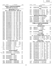
...X 10k 1/16W M-Ox. Part No. « Description Code JACK J903 J905 QJAKE0211CE09 X RCA JACK WHITE AB QJAKE0211CE04 X RCA JACK YELLOW AB Plug P302 ...Line Filter AC RCILP0179CEZZ+ X Coil AB RCILP0197CEZZ X Coil AB RCILB0131CEZZ X Coil (OSC) AB TRANSFORMERS T601 RTRNZ0731CEZZ X TRANSFORMER AD p U T602 RTRNF0213PEZZ X H-Volt Transformer AP U T702 RTRNW0003PEZZ X Power Transformer AE SWITCH S2501 QSW-K0202PEZZ+ X SWITCH AB S2502 QSW-K0202PEZZ+ X SWITCH AB S2503 QSW-K0202PEZZ+ X SWITCH AB S2504 QSW-K0202PEZZ+ X SWITCH AB S2505 QSW-K0202PEZZ+ X SWITCH...
...X 10k 1/16W M-Ox. Part No. « Description Code JACK J903 J905 QJAKE0211CE09 X RCA JACK WHITE AB QJAKE0211CE04 X RCA JACK YELLOW AB Plug P302 ...Line Filter AC RCILP0179CEZZ+ X Coil AB RCILP0197CEZZ X Coil AB RCILB0131CEZZ X Coil (OSC) AB TRANSFORMERS T601 RTRNZ0731CEZZ X TRANSFORMER AD p U T602 RTRNF0213PEZZ X H-Volt Transformer AP U T702 RTRNW0003PEZZ X Power Transformer AE SWITCH S2501 QSW-K0202PEZZ+ X SWITCH AB S2502 QSW-K0202PEZZ+ X SWITCH AB S2503 QSW-K0202PEZZ+ X SWITCH AB S2504 QSW-K0202PEZZ+ X SWITCH AB S2505 QSW-K0202PEZZ+ X SWITCH...
Service Manual
Page 22
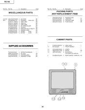
... Ref. VOL + CH VIDEO IN AUDIO 1-4 1-3 1-2 FRONT CABINET - 1-2 GCOVA0003GJSA X COVER - 1-3 HBDGB1001GJSB X BADGE AB 1-4 JBTN-0003GJSJ X Button(Power, - No. Part No. « Description Code MISCELLANEOUS PARTS ACC701 QACCDA015WJPZ X AC-CORD AE SP1 VSP0080PBL4YS X SPEAKER 32ohm 2W AE QCNW-2111PEZZ X WIRE (YBN) AB QCNW-2112PEZZ X WIRE (S) AB QCNW-2160PEZZ X WIRE (GBN) AC LHLDK0014PEZZ X AC CORD HOLDER AB LHLDZ0063PEZZ X HOLDER AB TLABM0002GJZZ X Model label mono voltge...
... Ref. VOL + CH VIDEO IN AUDIO 1-4 1-3 1-2 FRONT CABINET - 1-2 GCOVA0003GJSA X COVER - 1-3 HBDGB1001GJSB X BADGE AB 1-4 JBTN-0003GJSJ X Button(Power, - No. Part No. « Description Code MISCELLANEOUS PARTS ACC701 QACCDA015WJPZ X AC-CORD AE SP1 VSP0080PBL4YS X SPEAKER 32ohm 2W AE QCNW-2111PEZZ X WIRE (YBN) AB QCNW-2112PEZZ X WIRE (S) AB QCNW-2160PEZZ X WIRE (GBN) AC LHLDK0014PEZZ X AC CORD HOLDER AB LHLDZ0063PEZZ X HOLDER AB TLABM0002GJZZ X Model label mono voltge...
Service Manual
Page 23
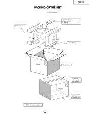
5 Wrapping Paper PACKING OF THE SET 5 Polyethylene Bag 19C140 Operation Manual Infrared R/C Unit 5 Batteries 5 Buffer Material FRONT 5 MARK : Not replacement items. 23 5 Packing Case REAR Use tape to fix the bottom side of packing case. Use 10 staples to fix the top side of packing case.
5 Wrapping Paper PACKING OF THE SET 5 Polyethylene Bag 19C140 Operation Manual Infrared R/C Unit 5 Batteries 5 Buffer Material FRONT 5 MARK : Not replacement items. 23 5 Packing Case REAR Use tape to fix the bottom side of packing case. Use 10 staples to fix the top side of packing case.
Service Manual
Page 24
...part of this publication may be reproduced, stored in a retrieval system, or transmitted in any form or by any means, electronic, mechanical, photocopying, recording, or otherwise, without prior written permission of the publisher. QRC0005-L Feb. 2004 Modify : SEMEX Design and Production Information Design base : JAPAN Production : SEMEX J B SHARP ELECTRONICA MEXICO S. A. 19C140... COPYRIGHT © 2004 BY SHARP CORPORATION ALL RIGHTS RESERVED. DE C. Quality & Reliability Control Center Blvd.
...part of this publication may be reproduced, stored in a retrieval system, or transmitted in any form or by any means, electronic, mechanical, photocopying, recording, or otherwise, without prior written permission of the publisher. QRC0005-L Feb. 2004 Modify : SEMEX Design and Production Information Design base : JAPAN Production : SEMEX J B SHARP ELECTRONICA MEXICO S. A. 19C140... COPYRIGHT © 2004 BY SHARP CORPORATION ALL RIGHTS RESERVED. DE C. Quality & Reliability Control Center Blvd.


