Product Manual
Page 5
commands 30 B FCC verification 15 Configuring and mounting the drive 17 Handling and static-discharge precautions 17 Jumper settings 18 Master/slave configuration 18 Cable-select option 19 Ultra ATA/66 cable 19 Drive mounting 19 ATA interface 21 ATA interface signals and connector pins 21 Supported ATA commands 23 Identify Drive command 24 Set Features command 29 S.M.A.R.T. iv U8 Family Product Manual, Rev.
commands 30 B FCC verification 15 Configuring and mounting the drive 17 Handling and static-discharge precautions 17 Jumper settings 18 Master/slave configuration 18 Cable-select option 19 Ultra ATA/66 cable 19 Drive mounting 19 ATA interface 21 ATA interface signals and connector pins 21 Supported ATA commands 23 Identify Drive command 24 Set Features command 29 S.M.A.R.T. iv U8 Family Product Manual, Rev.
Product Manual
Page 8
...-of master/slave drives that use cable select (CSEL) • SeaShield® innovative, shock-absorbing cover shields the drive against electrostatic discharge (ESD) and other handling damage. It also includes installation instructions and jumper settings. drive monitoring and reporting • Support for Read Multiple and Write Multiple commands • Support for autodetection of -the-art cache and on-the-fly error-correction algorithms • Full-track multiple-sector transfer capability without...
...-of master/slave drives that use cable select (CSEL) • SeaShield® innovative, shock-absorbing cover shields the drive against electrostatic discharge (ESD) and other handling damage. It also includes installation instructions and jumper settings. drive monitoring and reporting • Support for Read Multiple and Write Multiple commands • Support for autodetection of -the-art cache and on-the-fly error-correction algorithms • Full-track multiple-sector transfer capability without...

Product Manual
Page 9
...-track seek time (msec typical) 1.5 (read /write heads 4 3 2 1 Discs 2 2 1 1 Recording density BPI (bits/inch max) 349,374 Track density TPI (tracks/inch) 18,700 Areal density (Mbits/inch2 max) 6,536 Spindle speed (RPM) 5,400 Internal data-transfer rate (Mbits/ sec max) 285.5 I/O data-transfer rate (Mbytes/ sec max) 66.6 ATA data-transfer modes supported PIO modes 0-4 Multiword DMA modes 0-2 Ultra DMA modes 0-4 Cache buffer (Kbytes) 512 256-Kbyte cache is optional for quick reference. B Specification summary table The specifications listed...
...-track seek time (msec typical) 1.5 (read /write heads 4 3 2 1 Discs 2 2 1 1 Recording density BPI (bits/inch max) 349,374 Track density TPI (tracks/inch) 18,700 Areal density (Mbits/inch2 max) 6,536 Spindle speed (RPM) 5,400 Internal data-transfer rate (Mbits/ sec max) 285.5 I/O data-transfer rate (Mbytes/ sec max) 66.6 ATA data-transfer modes supported PIO modes 0-4 Multiword DMA modes 0-2 Ultra DMA modes 0-4 Cache buffer (Kbytes) 512 256-Kbyte cache is optional for quick reference. B Specification summary table The specifications listed...
Product Manual
Page 11
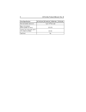
B Drive Specification Nonrecoverable read errors ST317221A ST313021A ST38410A ST34313A 1 per 1013 bits read Mean time between failures (power-on hours) 500,000 Contact start-stop cycles (25°C, 40% relative humidity) 50,000 SeaShield Yes 4 U8 Family Product Manual, Rev.
B Drive Specification Nonrecoverable read errors ST317221A ST313021A ST38410A ST34313A 1 per 1013 bits read Mean time between failures (power-on hours) 500,000 Contact start-stop cycles (25°C, 40% relative humidity) 50,000 SeaShield Yes 4 U8 Family Product Manual, Rev.

Product Manual
Page 12
... 1.1.1 Default logical geometry CHS Mode ST317221A ST313021A ST38410A Cylinders 16,383 16,383 16,383 Read/Write heads Sectors per track 16 63 16 63 16 63 ST34313A 8,944 15 63 LBA Mode When addressing either drive in LBA mode, all specifications are consecutively numbered from 0 to n-1, where n is the number of guaranteed sectors as defined above. 1.2 Physical organization Drive Model Read/Write heads (GMR) ST317221A 4 ST313021A 3 ST38410A 2 ST34313A 1 Number of discs 2 2 1 1 B 5 1.0 Drive specifications Unless...
... 1.1.1 Default logical geometry CHS Mode ST317221A ST313021A ST38410A Cylinders 16,383 16,383 16,383 Read/Write heads Sectors per track 16 63 16 63 16 63 ST34313A 8,944 15 63 LBA Mode When addressing either drive in LBA mode, all specifications are consecutively numbered from 0 to n-1, where n is the number of guaranteed sectors as defined above. 1.2 Physical organization Drive Model Read/Write heads (GMR) ST317221A 4 ST313021A 3 ST38410A 2 ST34313A 1 Number of discs 2 2 1 1 B 5 1.0 Drive specifications Unless...

Product Manual
Page 13
... Product Manual, Rev. The specifications in the table below are measured using drive diagnostics. All times are defined as follows: B 1.3 Recording and interface technology Interface ATA Recording method 24/26 EPRML Recording density BPI (bits/inch) 349,374 Track density TPI (tracks/inch) Areal density (Mbits/inch2 max) 18,700 6,536 Spindle speed (RPM) (± 0.2%) 5,400 Internal data-transfer rate (Mbits/sec max) 285.5 I/O data-transfer rate (Mbytes/sec max) 16.6 (PIO mode...
... Product Manual, Rev. The specifications in the table below are measured using drive diagnostics. All times are defined as follows: B 1.3 Recording and interface technology Interface ATA Recording method 24/26 EPRML Recording density BPI (bits/inch) 349,374 Track density TPI (tracks/inch) Areal density (Mbits/inch2 max) 18,700 6,536 Spindle speed (RPM) (± 0.2%) 5,400 Internal data-transfer rate (Mbits/sec max) 285.5 I/O data-transfer rate (Mbytes/sec max) 16.6 (PIO mode...

Product Manual
Page 14
... are formatted, benchmark tests that include command overhead or measure logical seeks may produce results that the drive spindle reaches operating speed. However, due to the manner in which these specifications. 1.6 Start/stop (sec) 10 (typical) 10 (typical) 10 (typical) 1.7 Power specifications The drive receives DC power (+5V or +12V) through a four-pin standard drive power connector. 1.7.1 Power consumption Power requirements for the drives are listed in both directions. • Average seek time...
... are formatted, benchmark tests that include command overhead or measure logical seeks may produce results that the drive spindle reaches operating speed. However, due to the manner in which these specifications. 1.6 Start/stop (sec) 10 (typical) 10 (typical) 10 (typical) 1.7 Power specifications The drive receives DC power (+5V or +12V) through a four-pin standard drive power connector. 1.7.1 Power consumption Power requirements for the drives are listed in both directions. • Average seek time...

Product Manual
Page 15
...; Operating power and current Operating power is measured using only random seeks with the heads in a random track location. • Standby mode During Standby mode, the drive accepts commands, but the drive is not spinning, and the servo and read/write electronics are active. Seek mode power represents the worst-case power consumption, using 40 percent random seeks, 40 percent read/write mode (1 write for worst-case information. • Read/Write power and current Read/write power is measured with the drive up to speed, with...
...; Operating power and current Operating power is measured using only random seeks with the heads in a random track location. • Standby mode During Standby mode, the drive accepts commands, but the drive is not spinning, and the servo and read/write electronics are active. Seek mode power represents the worst-case power consumption, using 40 percent random seeks, 40 percent read/write mode (1 write for worst-case information. • Read/Write power and current Read/write power is measured with the drive up to speed, with...
Product Manual
Page 17
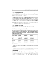
... to operate with a maximum of time. The drive features the following power-management modes: Power Modes Heads Spindle Buffer Active Tracking Rotating Enabled Idle Tracking Rotating Enabled Standby Parked Stopped Enabled Sleep Parked Stopped Disabled • Active mode The drive is in Active mode during the read /write current. 1.7.3 Voltage tolerance Voltage tolerance (including noise): 5V ± 5% and 12V ± 10% 1.7.4 Power-management modes The drive provides programmable power management to Active mode any time disc access...
... to operate with a maximum of time. The drive features the following power-management modes: Power Modes Heads Spindle Buffer Active Tracking Rotating Enabled Idle Tracking Rotating Enabled Standby Parked Stopped Enabled Sleep Parked Stopped Disabled • Active mode The drive is in Active mode during the read /write current. 1.7.3 Voltage tolerance Voltage tolerance (including noise): 5V ± 5% and 12V ± 10% 1.7.4 Power-management modes The drive provides programmable power management to Active mode any time disc access...

Product Manual
Page 18
... and begins counting down from the host. Actual drive case temperature should not exceed 65°C (149°F) within the operating ambient conditions. U8 Family Product Manual, Rev. In Sleep mode, the drive buffer is disabled, the heads are shown in Figure 3 on page 20. The drive leaves Sleep mode after receiving a Sleep command from its specified delay times to 112°F (44°C) at 10,000...
... and begins counting down from the host. Actual drive case temperature should not exceed 65°C (149°F) within the operating ambient conditions. U8 Family Product Manual, Rev. In Sleep mode, the drive buffer is disabled, the heads are shown in Figure 3 on page 20. The drive leaves Sleep mode after receiving a Sleep command from its specified delay times to 112°F (44°C) at 10,000...
Product Manual
Page 21
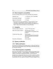
.... 1.11 Reliability Nonrecoverable read errors Mean time between failures Contact start-stop cycles Preventive maintenance 1 per 1013 bits read, max 500,000 power-on hours (nominal power, 25°C ambient temperature) 50,000 cycles (at nominal voltage and temperature, with 60 cycles per hour and a 50% duty cycle) None required 1.12 Agency certification 1.12.1 Safety certification The drives are tested in a representative computer...
.... 1.11 Reliability Nonrecoverable read errors Mean time between failures Contact start-stop cycles Preventive maintenance 1 per 1013 bits read, max 500,000 power-on hours (nominal power, 25°C ambient temperature) 50,000 cycles (at nominal voltage and temperature, with 60 cycles per hour and a 50% duty cycle) None required 1.12 Agency certification 1.12.1 Safety certification The drives are tested in a representative computer...

Product Manual
Page 22
... such interference in enclosures as an external device). Operation with the Australia/ New Zealand Standard AS/NZS3548 1995 and meet the Electromagnetic Compatibility (EMC) Framework requirements of the device is required. However, there is no Federal Communications Commission verification or certification of Australia's Spectrum Management Agency (SMA). 1.12.3 FCC verification These drives are intended to Subpart J, Part 15 of...
... such interference in enclosures as an external device). Operation with the Australia/ New Zealand Standard AS/NZS3548 1995 and meet the Electromagnetic Compatibility (EMC) Framework requirements of the device is required. However, there is no Federal Communications Commission verification or certification of Australia's Spectrum Management Agency (SMA). 1.12.3 FCC verification These drives are intended to Subpart J, Part 15 of...
Product Manual
Page 24
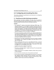
... the connector pins or the printed circuit board. • Do not remove the factory-installed labels from the SeaShell. Do not press down on the drive top cover. • Always rest the drive on a grounded wrist strap, or ground yourself frequently by its static-shielded bag until you are used to complete the installation. Removal voids the warranty. Some factoryinstalled labels contain information needed...
... the connector pins or the printed circuit board. • Do not remove the factory-installed labels from the SeaShell. Do not press down on the drive top cover. • Always rest the drive on a grounded wrist strap, or ground yourself frequently by its static-shielded bag until you are used to complete the installation. Removal voids the warranty. Some factoryinstalled labels contain information needed...

Product Manual
Page 25
... or single drive Drive is used to configure the drive as a master with a non-ATA-compatible slave. Master/slave jumper settings Master or single drive. Use this jumper setting only if the drive does not work as a master or a slave. Remove all jumpers. Use the following settings to configure the drive for a master or single-drive operation with a non-ATAcompatible slave Cable select 7531 8642 Figure 2. Drive as master with no jumpers installed. It is configured at the factory for operation. The drive is the 8-pin dual header between the interface connector and the...
... or single drive Drive is used to configure the drive as a master with a non-ATA-compatible slave. Master/slave jumper settings Master or single drive. Use this jumper setting only if the drive does not work as a master or a slave. Remove all jumpers. Use the following settings to configure the drive for a master or single-drive operation with a non-ATAcompatible slave Cable select 7531 8642 Figure 2. Drive as master with no jumpers installed. It is configured at the factory for operation. The drive is the 8-pin dual header between the interface connector and the...
Product Manual
Page 26
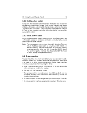
... cable uses even-numbered conductors connected to the ground pins to run Ultra DMA mode 3 and 4. See Figure 4 on page 20 for cooling. • Use ...manual to determine whether your computer supports this option. 2.2.3 Ultra ATA/66 cable An 80-conductor 40-pin cable is more than 18 inches long. Note. To enable cable select, set a jumper on the interface bus. The drive supports both host and drive cable detection. The host detects the 80-conductor cable by their physical position on the interface bus. Master and slave drives are determined by sampling pin 34, CBLID-, on pins...
... cable uses even-numbered conductors connected to the ground pins to run Ultra DMA mode 3 and 4. See Figure 4 on page 20 for cooling. • Use ...manual to determine whether your computer supports this option. 2.2.3 Ultra ATA/66 cable An 80-conductor 40-pin cable is more than 18 inches long. Note. To enable cable select, set a jumper on the interface bus. The drive supports both host and drive cable detection. The host detects the 80-conductor cable by their physical position on the interface bus. Master and slave drives are determined by sampling pin 34, CBLID-, on pins...

Product Manual
Page 30
... Device Diagnostics Flush Cache Format Track Identify Device Initialize Device Parameters Read Buffer Read DMA Read Multiple Read Sectors Read Verify Sectors Read Native Max Address Recalibrate Seek Set Features Set Multiple Mode Set Max Address S.M.A.R.T. Write Buffer Write DMA 92H 90H E7H 50H ECH 91H E4H C8H, C9H C4H 20H, 21H 40H, 41H F8H 10H 70H EFH C6H F9H B0H E8H CAH, CBH B 23 3.1.1 Supported ATA commands The following table lists ATA-standard commands that the drive supports. U8 Family Product Manual...
... Device Diagnostics Flush Cache Format Track Identify Device Initialize Device Parameters Read Buffer Read DMA Read Multiple Read Sectors Read Verify Sectors Read Native Max Address Recalibrate Seek Set Features Set Multiple Mode Set Max Address S.M.A.R.T. Write Buffer Write DMA 92H 90H E7H 50H ECH 91H E4H C8H, C9H C4H 20H, 21H 40H, 41H F8H 10H 70H EFH C6H F9H B0H E8H CAH, CBH B 23 3.1.1 Supported ATA commands The following table lists ATA-standard commands that the drive supports. U8 Family Product Manual...

Product Manual
Page 31
... hex) Write Multiple C5H Write Sectors 30H, 31H ATA-standard power-management commands Check Power Mode 98H or E5H Idle 97H or E3H Idle Immediate 95H or E1H Sleep 99H or E6H Standby 96H or E2H Standby Immediate 94H or E0H ATA-standard security commands Security Set Password F1H Security Unlock F2H Security Erase Prepare F3H Security Erase Unit F4H Security Freeze Lock F5H Security Disable Password F6H 3.1.2 Identify Drive command The Identify Drive command (command code ECH) transfers information about the drive to zero...
... hex) Write Multiple C5H Write Sectors 30H, 31H ATA-standard power-management commands Check Power Mode 98H or E5H Idle 97H or E3H Idle Immediate 95H or E1H Sleep 99H or E6H Standby 96H or E2H Standby Immediate 94H or E0H ATA-standard security commands Security Set Password F1H Security Unlock F2H Security Erase Prepare F3H Security Erase Unit F4H Security Freeze Lock F5H Security Disable Password F6H 3.1.2 Identify Drive command The Identify Drive command (command code ECH) transfers information about the drive to zero...

Product Manual
Page 33
... track Current capacity in sectors Number of sectors transferred during a Read Multiple or Write Multiple command xxxxH xxxxH xxxxH Total number of user-addressable LBA sectors available ST317221A = 33,683,328 ST313021A = 25,434,228 ST38410A = 16,841,664 ST34313A = 8,452,080 Retired Multiword DMA active and modes supported (see note following this table) 0000H xx07H Advanced PIO modes supported (modes 3 and 4 supported) 0003H 26 U8 Family Product Manual, Rev.
... track Current capacity in sectors Number of sectors transferred during a Read Multiple or Write Multiple command xxxxH xxxxH xxxxH Total number of user-addressable LBA sectors available ST317221A = 33,683,328 ST313021A = 25,434,228 ST38410A = 16,841,664 ST34313A = 8,452,080 Retired Multiword DMA active and modes supported (see note following this table) 0000H xx07H Advanced PIO modes supported (modes 3 and 4 supported) 0003H 26 U8 Family Product Manual, Rev.

Product Manual
Page 34
... PIO cycle time with IORDY flow control (120 nsec) ATA-reserved Queue depth ATA-reserved Major version number Minor version number Command sets supported Command sets supported Command sets support extension Command sets enabled Command sets enabled Command sets enable extension Ultra DMA support and current mode (see note following this table) Security erase time Enhanced security erase time 27 Value 0078H 0078H 00F0H 0078H 0000H 0000H 0000H 003EH 0000H 346BH 4009H 4000H xxxxH xxxxH xxxxH xx1FH 0000H 0000H U8 Family Product Manual, Rev.
... PIO cycle time with IORDY flow control (120 nsec) ATA-reserved Queue depth ATA-reserved Major version number Minor version number Command sets supported Command sets supported Command sets support extension Command sets enabled Command sets enabled Command sets enable extension Ultra DMA support and current mode (see note following this table) Security erase time Enhanced security erase time 27 Value 0078H 0078H 00F0H 0078H 0000H 0000H 0000H 003EH 0000H 346BH 4009H 4000H xxxxH xxxxH xxxxH xx1FH 0000H 0000H U8 Family Product Manual, Rev.
Product Manual
Page 35
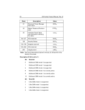
... DMA mode 2 is supported. 3 Ultra DMA mode 3 is currently active. B Word Description Value 91 Advanced Power Management value 0040H 92 Master Password Revision code FFFEH 93 Hardware Reset Value (see description following this table) xxxxH 94-127 ATA-reserved 0000H 128 Security Status 0001H 129-159 Seagate-reserved xxxxH 160-254 ATA-reserved 0000H 255 Integrity word xxA5H Note. 28 U8 Family Product Manual...
... DMA mode 2 is supported. 3 Ultra DMA mode 3 is currently active. B Word Description Value 91 Advanced Power Management value 0040H 92 Master Password Revision code FFFEH 93 Hardware Reset Value (see description following this table) xxxxH 94-127 ATA-reserved 0000H 128 Security Status 0001H 129-159 Seagate-reserved xxxxH 160-254 ATA-reserved 0000H 255 Integrity word xxA5H Note. 28 U8 Family Product Manual...

