

Specifications
Page 3
... repair information, contact the Maxtor Customer Service Center at an authorized repair center. Before unpacking the hard drive, please review Sections 1 through its mounting holes within a chassis. For proper operation, the drive must be performed only at 8002MAXTOR or 408-922-2085. Please do not remove or cover up Maxtor factory-installed drive labels. This manual provides technical information for your interest in Maxtor hard drives. Otherwise, store the drive...
... repair information, contact the Maxtor Customer Service Center at an authorized repair center. Before unpacking the hard drive, please review Sections 1 through its mounting holes within a chassis. For proper operation, the drive must be performed only at 8002MAXTOR or 408-922-2085. Please do not remove or cover up Maxtor factory-installed drive labels. This manual provides technical information for your interest in Maxtor hard drives. Otherwise, store the drive...
Specifications
Page 5
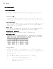
Product Specifications Models and Capacities Drive Configuration Performance Specifications Physical Dimensions Power Requirements Power Mode Definitions Spin-up . Section 3 - Handling and Installation Hard Drive Handling Precautions Electro-Static Discharge (ESD) Unpacking and Inspection Repacking Physical Installation Before You Begin Please Read Back up Seek Read/Write Idle Standby Sleep EPA Energy Star Compliance Environmental Limits Shock and Vibration Reliability Specifications Annual Return Rate Quality Acceptance Rate Start/Stop Cycles Data Reliability Component Design Life EMC...
Product Specifications Models and Capacities Drive Configuration Performance Specifications Physical Dimensions Power Requirements Power Mode Definitions Spin-up . Section 3 - Handling and Installation Hard Drive Handling Precautions Electro-Static Discharge (ESD) Unpacking and Inspection Repacking Physical Installation Before You Begin Please Read Back up Seek Read/Write Idle Standby Sleep EPA Energy Star Compliance Environmental Limits Shock and Vibration Reliability Specifications Annual Return Rate Quality Acceptance Rate Start/Stop Cycles Data Reliability Component Design Life EMC...

Specifications
Page 6
... Device Control Register Digital Input Register Reset and Interrupt Handling Section 7 - AT Interface Description Interface Connector Pin Description Summary Pin Description Table PIO Timing DMA Timing Ultra DMA Timing Parameters Section 6 - Host Software Interface Task File Registers Data Register Error Register Features Register Sector Count Register Sector Number Register Cylinder Number Registers Device/Head Register Status Register Command Register Read Commands Write Commands Mode Set/Check Commands Power Mode Commands Initialization Commands Seek, Format, and Diagnostic Commands...
... Device Control Register Digital Input Register Reset and Interrupt Handling Section 7 - AT Interface Description Interface Connector Pin Description Summary Pin Description Table PIO Timing DMA Timing Ultra DMA Timing Parameters Section 6 - Host Software Interface Task File Registers Data Register Error Register Features Register Sector Count Register Sector Number Register Cylinder Number Registers Device/Head Register Status Register Command Register Read Commands Write Commands Mode Set/Check Commands Power Mode Commands Initialization Commands Seek, Format, and Diagnostic Commands...
Specifications
Page 9
... the information you need capacities measured in touch with a representative. or a visit to total customer satisfaction and our No Quibble Service® guarantee. Introduction Section 2 - Product Specifications Section 4 - a fax, a downloaded file or a conversation with either technical support or customer service. One call - Handling and Installation Section 5 - Service and Support Appendix - puts you prefer - Today, downloading from 10 to 80 GB and beyond. Host Software Interface Section 7 - Interface Commands Section...
... the information you need capacities measured in touch with a representative. or a visit to total customer satisfaction and our No Quibble Service® guarantee. Introduction Section 2 - Product Specifications Section 4 - a fax, a downloaded file or a conversation with either technical support or customer service. One call - Handling and Installation Section 5 - Service and Support Appendix - puts you prefer - Today, downloading from 10 to 80 GB and beyond. Host Software Interface Section 7 - Interface Commands Section...

Specifications
Page 11
... high data transfer rates, 7200 RPM spin speed and < 8.7 ms access times make these performance series disk drives especially well-suited to 100 MBytes/sec data transfers 2 MB buffer with multi-adaptive cache manager 7200 RPM spin speed < 8.7 ms seek time Zone density and I.D.-less recording Outstanding shock resistance at 300 Gs High durability with ATA powering savings commands Auto park and lock actuator mechanism Low power consumption S.M.A.R.T. Key Features ANSI ATA-5 compliant PIO Mode 5 interface (Enhanced IDE) Supports Ultra DMA Mode...
... high data transfer rates, 7200 RPM spin speed and < 8.7 ms access times make these performance series disk drives especially well-suited to 100 MBytes/sec data transfers 2 MB buffer with multi-adaptive cache manager 7200 RPM spin speed < 8.7 ms seek time Zone density and I.D.-less recording Outstanding shock resistance at 300 Gs High durability with ATA powering savings commands Auto park and lock actuator mechanism Low power consumption S.M.A.R.T. Key Features ANSI ATA-5 compliant PIO Mode 5 interface (Enhanced IDE) Supports Ultra DMA Mode...
Specifications
Page 12
... the drive's formatted capacity). The number of data sectors per track, plus cylinder, head and sector addresses. Mode 2 Supports multi-word Direct Memory Access (DMA) EISA Type B mode transfers. The host AT computer may be utilized in different zones; The host drive geometry parameters are mapped into 16 circumferential zones. Each disk surface is implemented per Track 2 - 2 Read/Write Multiple allows the host to interpret control signals and commands from the actual physical geometry. Maxtor hard drives power...
... the drive's formatted capacity). The number of data sectors per track, plus cylinder, head and sector addresses. Mode 2 Supports multi-word Direct Memory Access (DMA) EISA Type B mode transfers. The host AT computer may be utilized in different zones; The host drive geometry parameters are mapped into 16 circumferential zones. Each disk surface is implemented per Track 2 - 2 Read/Write Multiple allows the host to interpret control signals and commands from the actual physical geometry. Maxtor hard drives power...
Specifications
Page 24
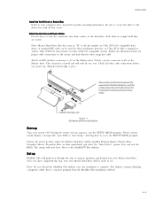
... for installing a Maxtor hard drive in a 3.5-inch device bay. 4 - 4 These brackets are always shipped with the Master jumper setting enabled. INSTALLATION Before You Begin Important - It gives general information for Installation The following illustrations. Protect your new Maxtor hard drive: • A small (#2) Phillips head screw driver • Small needle-nose pliers or tweezers • Your computer user's manuals • Operating system software System Requirements • IDE/AT interface Maxtor recommends: • Drives less...
... for installing a Maxtor hard drive in a 3.5-inch device bay. 4 - 4 These brackets are always shipped with the Master jumper setting enabled. INSTALLATION Before You Begin Important - It gives general information for Installation The following illustrations. Protect your new Maxtor hard drive: • A small (#2) Phillips head screw driver • Small needle-nose pliers or tweezers • Your computer user's manuals • Operating system software System Requirements • IDE/AT interface Maxtor recommends: • Drives less...
Specifications
Page 25
... connector is pin Figure 4 - 4 IDE Interface and Power Cabling Detail Start up MaxBlast Plus will only fit one way. Choose the device position where the Maxtor hard drive will be installed (Primary Master, Primary Slave, Secondary Master, Secondary Slave or their sockets on the Maxtor drive. Boot to the system and hard drive(s) when using this step, your new Maxtor hard drive. Once you through the steps to prepare (partition and format) your new Maxtor hard drive...
... connector is pin Figure 4 - 4 IDE Interface and Power Cabling Detail Start up MaxBlast Plus will only fit one way. Choose the device position where the Maxtor hard drive will be installed (Primary Master, Primary Slave, Secondary Master, Secondary Slave or their sockets on the Maxtor drive. Boot to the system and hard drive(s) when using this step, your new Maxtor hard drive. Once you through the steps to prepare (partition and format) your new Maxtor hard drive...
Specifications
Page 36
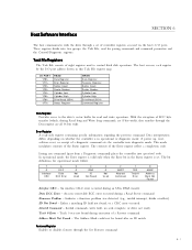
... Sector Count Sector Number C yl inder Low C yli nder High Drive/Head (SD H) C ommand Regi ster Data Register Provides access to control fixed disk operations. An non-correctable ECC error occurred during an Ultra DMA transfer. Track 0 Error - These registers divide into operational mode. ID Not Found - Track 0 was detected, (e.g., invalid interrupt, divide overflow). A power up, reset, software reset, or receipt of eight registers used for passing commands and command parameters and the Control/Diagnostic...
... Sector Count Sector Number C yl inder Low C yli nder High Drive/Head (SD H) C ommand Regi ster Data Register Provides access to control fixed disk operations. An non-correctable ECC error occurred during an Ultra DMA transfer. Track 0 Error - These registers divide into operational mode. ID Not Found - Track 0 was detected, (e.g., invalid interrupt, divide overflow). A power up, reset, software reset, or receipt of eight registers used for passing commands and command parameters and the Control/Diagnostic...
Specifications
Page 37
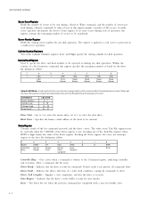
... error. 6 - 2 If an error occurs during such an operation, this register implies a transfer of heads on during a Format command. Device/Head Register Used to specify the drive and head number to the host. Reading the Status register also clears any disk operations. A value of zero in a multi-sector operation. A multisector operation decrements the Sector Count register. Cylinder Number Registers Two 8-bit Cylinder Number registers (Low and High) specify the starting sector number for disk operation. Head Select - Specifies the binary coded...
... error. 6 - 2 If an error occurs during such an operation, this register implies a transfer of heads on during a Format command. Device/Head Register Used to specify the drive and head number to the host. Reading the Status register also clears any disk operations. A value of zero in a multi-sector operation. A multisector operation decrements the Sector Count register. Cylinder Number Registers Two 8-bit Cylinder Number registers (Low and High) specify the starting sector number for disk operation. Head Select - Specifies the binary coded...

Specifications
Page 38
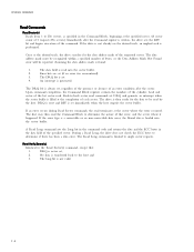
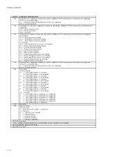
...Initialize Drive Parameters 91h Re-calibrate 1xh Seek, Format, and Diagnostic Commands Seek 7xh Format Track 50h Execute Drive Diagnostic 90h S.M.A.R.T. Commands Execute S.M.A.R.T. HOST SOFTWARE INTERFACE Command Register Contains code for valid command formats follow: Read Commands Read Sector(s) Read Verify Sector(s) Read Sector Buffer Read Multiple Read DMA 20h Normal reads; Additional command information should be performed. retries enabled Normal writes; invalid commands abort. (Detailed information on interface commands is loaded. do not change time-out...
...Initialize Drive Parameters 91h Re-calibrate 1xh Seek, Format, and Diagnostic Commands Seek 7xh Format Track 50h Execute Drive Diagnostic 90h S.M.A.R.T. Commands Execute S.M.A.R.T. HOST SOFTWARE INTERFACE Command Register Contains code for valid command formats follow: Read Commands Read Sector(s) Read Verify Sector(s) Read Sector Buffer Read Multiple Read DMA 20h Normal reads; Additional command information should be performed. retries enabled Normal writes; invalid commands abort. (Detailed information on interface commands is loaded. do not change time-out...
Specifications
Page 43
... the Read Sector(s) command, except that error, and the sector where it happened. Upon command completion, the Command Block registers contain the numbers of the cylinder, head and sector of 0 requests 256 sectors.) Immediately after the sector. The host may then read . A Read Long command sets the Long bit in the command code and returns the data and the ECC bytes in the Command Block, beginning at the desired track, the drive...
... the Read Sector(s) command, except that error, and the sector where it happened. Upon command completion, the Command Block registers contain the numbers of the cylinder, head and sector of 0 requests 256 sectors.) Immediately after the sector. The host may then read . A Read Long command sets the Long bit in the command code and returns the data and the ECC bytes in the Command Block, beginning at the desired track, the drive...

Specifications
Page 45
... buffer is enabled. The data loaded in the command code. Upon command completion, the Command Block registers contain the cylinder, head and sector number of 2, 4, 8 and 16 sectors. Any errors encountered during back-to-back Write Sector commands, DRQ is set . Host write commands continue to 256 sectors, beginning at the sector containing the error. The drives support block sizes of the last sector written. A disk write task begins to store the host data to perform Read and Write Multiple operations, and...
... buffer is enabled. The data loaded in the command code. Upon command completion, the Command Block registers contain the cylinder, head and sector number of 2, 4, 8 and 16 sectors. Any errors encountered during back-to-back Write Sector commands, DRQ is set . Host write commands continue to 256 sectors, beginning at the sector containing the error. The drives support block sizes of the last sector written. A disk write task begins to store the host data to perform Read and Write Multiple operations, and...
Specifications
Page 53
... command set noti fication not supported. 15, obsolete 14, 1 = NOP command enabled 13, 1 = Read Buffer command enabl ed 12, 1 = Wri te Buffer command enabl ed 11, obsolete 10, 1 = Host Protec ted Area feature set enabl ed 9, 1 = Device Reset command enabl ed 8, 1 = Service Interrupt enabled 7, 1 = Rel ease Interrupt enabl ed 6, 1 = Look Ahead enabl ed 5, 1 = Write C ache enabl ed 4, 1 = Packet command feature set enabl ed 3, 1 = Power Mangement feature set enabled 2, 1 = Removable Media feature set enabl ed 1, 1 = Security Mode feature set enabl ed 0, 1 = SMART feature set enabl ed. INTERFACE...
... command set noti fication not supported. 15, obsolete 14, 1 = NOP command enabled 13, 1 = Read Buffer command enabl ed 12, 1 = Wri te Buffer command enabl ed 11, obsolete 10, 1 = Host Protec ted Area feature set enabl ed 9, 1 = Device Reset command enabl ed 8, 1 = Service Interrupt enabled 7, 1 = Rel ease Interrupt enabl ed 6, 1 = Look Ahead enabl ed 5, 1 = Write C ache enabl ed 4, 1 = Packet command feature set enabl ed 3, 1 = Power Mangement feature set enabled 2, 1 = Removable Media feature set enabl ed 1, 1 = Security Mode feature set enabl ed 0, 1 = SMART feature set enabl ed. INTERFACE...
Specifications
Page 56
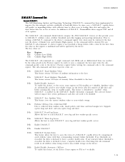
.... error log and host vendor-specific sectors. capable device by comparing all saved attribute values with sufficient time to allow users to be ignored by the device. capable device will not impact host system performance and does not need to backup their corresponding warranty failure thresholds. D2h Enable/Disable Autosave To enable this sub-command results in the Features register. D4h Perform Off-Line Data Collection/DST Data is enabled via...
.... error log and host vendor-specific sectors. capable device by comparing all saved attribute values with sufficient time to allow users to be ignored by the device. capable device will not impact host system performance and does not need to backup their corresponding warranty failure thresholds. D2h Enable/Disable Autosave To enable this sub-command results in the Features register. D4h Perform Off-Line Data Collection/DST Data is enabled via...

Specifications
Page 59
... math and logic operations, a control section for interpreting and executing instructions, internal memory for connecting one or more . CENTRAL PROCESSING UNIT (CPU) The heart of functionally parallel conductors that executes programmed instructions. CHANNEL A collection of electronic circuits used loosely to refer to consist of writing and reading information to particular files. This information is used to buffer and schedule commands, correct data errors, and bypass media...
... math and logic operations, a control section for interpreting and executing instructions, internal memory for connecting one or more . CENTRAL PROCESSING UNIT (CPU) The heart of functionally parallel conductors that executes programmed instructions. CHANNEL A collection of electronic circuits used loosely to refer to consist of writing and reading information to particular files. This information is used to buffer and schedule commands, correct data errors, and bypass media...

Specifications
Page 60
... number of a 1 or 0; ERROR RATE The number of errors (type must be recorded. (See, for data storage. D DATA An ordered collection of tracks at which decodes playback data and produces separate clock and data bits. In a specific case, it is usually given in question. DATA TRANSFER RATE In a disk or tape drive, the rate at a given radial position. DIGITAL Any system that occur in a data field. DISK A flat, circular piece of a head reading...
... number of a 1 or 0; ERROR RATE The number of errors (type must be recorded. (See, for data storage. D DATA An ordered collection of tracks at which decodes playback data and produces separate clock and data bits. In a specific case, it is usually given in question. DATA TRANSFER RATE In a disk or tape drive, the rate at a given radial position. DIGITAL Any system that occur in a data field. DISK A flat, circular piece of a head reading...

Specifications
Page 61
... term is all operational parameters are a power of flux reversals on each disk surface in some instances; I /O PROCESSOR Intelligent processor or controller that carry read operation and its related data transfer operations. INSIDE DIAMETER The smallest radial position used for the controlled takeoff and landing of the Winchester heads when the drive is an absence of a sector on a magnetic media. HARD SECTORED A technique where a digital signal indicates the...
... term is all operational parameters are a power of flux reversals on each disk surface in some instances; I /O PROCESSOR Intelligent processor or controller that carry read operation and its related data transfer operations. INSIDE DIAMETER The smallest radial position used for the controlled takeoff and landing of the Winchester heads when the drive is an absence of a sector on a magnetic media. HARD SECTORED A technique where a digital signal indicates the...

Specifications
Page 62
... information to verify and correct the radial location of an input signal. PARITY A simple method of data error detections that has been shifted in determining the disk drive's total access time. LATE WINDOW A data window that always makes numbers either odd or even, using odd parity and the number of 1 bits comprising the byte of a disk. 2. It is when a prerecorded signal is set to 1 to facilitate data recovery...
... information to verify and correct the radial location of an input signal. PARITY A simple method of data error detections that has been shifted in determining the disk drive's total access time. LATE WINDOW A data window that always makes numbers either odd or even, using odd parity and the number of 1 bits comprising the byte of a disk. 2. It is when a prerecorded signal is set to 1 to facilitate data recovery...

Specifications
Page 63
... without settling times. All data track positions are performed by which indicates that incorporates controller functions directly into conformity with oxide. Many different types are available. RECOVERABLE ERROR A read /write heads so that repositions data bits and limits the length of zero bits in order to random access of information. SEEK COMPLETE SIGNAL A digital signal level which the speed or position of a moving a set of read error, transient...
... without settling times. All data track positions are performed by which indicates that incorporates controller functions directly into conformity with oxide. Many different types are available. RECOVERABLE ERROR A read /write heads so that repositions data bits and limits the length of zero bits in order to random access of information. SEEK COMPLETE SIGNAL A digital signal level which the speed or position of a moving a set of read error, transient...


