

Assembly Manual
Page 1
... this machine before assembly. 2. Nautilus, Inc. (www.nautilus.com) trademarks include NAUTILUS®, BOWFLEX®, SCHWINN® and UNIVERSAL® and respective logos. Read and understand the "Important Safety Instructions" before first use only genuine...parts. When attaching 2 pieces, lightly lift and look through the bolt holes to loosen, unless instructed otherwise. 4. Important Safety Instructions Schwinn ® EVO Airdyne Assembly Manual 003-3241.021510.A This icon means a potentially hazardous situation which, if not avoided, could compromise the safety and can lead...
... this machine before assembly. 2. Nautilus, Inc. (www.nautilus.com) trademarks include NAUTILUS®, BOWFLEX®, SCHWINN® and UNIVERSAL® and respective logos. Read and understand the "Important Safety Instructions" before first use only genuine...parts. When attaching 2 pieces, lightly lift and look through the bolt holes to loosen, unless instructed otherwise. 4. Important Safety Instructions Schwinn ® EVO Airdyne Assembly Manual 003-3241.021510.A This icon means a potentially hazardous situation which, if not avoided, could compromise the safety and can lead...

Assembly Manual
Page 2
Item Qty Description 1 1 Seat 2 1 Seat Post 3 1 Locking Knob (Seat) 4 1 Console 5 1 Console Mast 6 1 Locking Knob (Wheel) 7 1 Spring, Locking Knob 8 1 Frame Assembly (includes Fan Assembly) Item Qty Description 9 1 Pedal, Left 10 1 Arm, Left 11 2 Hand Grip 12 2 Foot Rest Cover 13 1 Stabilizer, Front 14 1 Pedal, Right 15 1 Arm, Right 16 1 Stabilizer, Rear 2 Parts * Fan Assembly removed for clarity.
Item Qty Description 1 1 Seat 2 1 Seat Post 3 1 Locking Knob (Seat) 4 1 Console 5 1 Console Mast 6 1 Locking Knob (Wheel) 7 1 Spring, Locking Knob 8 1 Frame Assembly (includes Fan Assembly) Item Qty Description 9 1 Pedal, Left 10 1 Arm, Left 11 2 Hand Grip 12 2 Foot Rest Cover 13 1 Stabilizer, Front 14 1 Pedal, Right 15 1 Arm, Right 16 1 Stabilizer, Rear 2 Parts * Fan Assembly removed for clarity.
Assembly Manual
Page 3
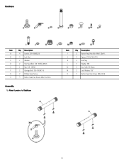
Hardware Item Qty Description A 4 Leveler, 3/8-16UNCx29 B 4 Lock Nut C 2 Washer D 2 Hex Head Bolt, 3/8-16UNC-88mm E 2 Nut, 3/8-16UNC F 2 Carriage Bolt, 3/8-16UNC-18 G 2 Phillips Head Screw H 4 Button Head Hex Screw, M6x1.0x12mm Assembly 1. Attach Levelers to Stabilizers Item Qty Description I 2 Button Head Hex Bolt, M8x1.25x41L J 4 Spacer, D10.5x15.5xT2.5 K 2 End Plug L 2 Washer, M8 M 2 Nut, M8x1.25 Nylon N 2 Lock Washer, 3/8" O 2 Button Head Hex Screw, M5x0.8x16 3
Hardware Item Qty Description A 4 Leveler, 3/8-16UNCx29 B 4 Lock Nut C 2 Washer D 2 Hex Head Bolt, 3/8-16UNC-88mm E 2 Nut, 3/8-16UNC F 2 Carriage Bolt, 3/8-16UNC-18 G 2 Phillips Head Screw H 4 Button Head Hex Screw, M6x1.0x12mm Assembly 1. Attach Levelers to Stabilizers Item Qty Description I 2 Button Head Hex Bolt, M8x1.25x41L J 4 Spacer, D10.5x15.5xT2.5 K 2 End Plug L 2 Washer, M8 M 2 Nut, M8x1.25 Nylon N 2 Lock Washer, 3/8" O 2 Button Head Hex Screw, M5x0.8x16 3
Assembly Manual
Page 4
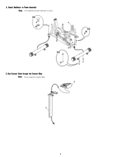
Run Console Cable through the Console Mast Note: Do not crimp the Console Cable. 4 Attach Stabilizers to Frame Assembly Note: Fan Assembly has been removed for clarity. 3. 2.
Run Console Cable through the Console Mast Note: Do not crimp the Console Cable. 4 Attach Stabilizers to Frame Assembly Note: Fan Assembly has been removed for clarity. 3. 2.

Assembly Manual
Page 5
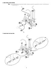
Place all excess cable in the Console Mast. 5. Attach Right and Left Arms to Frame Assembly Note: Do not crimp the Console Cable. Attach Console and Console Mast to Frame Assembly 5 4. Connect the Console Cable to the fan sensor on the right side of the Fan Assembly.
Place all excess cable in the Console Mast. 5. Attach Right and Left Arms to Frame Assembly Note: Do not crimp the Console Cable. Attach Console and Console Mast to Frame Assembly 5 4. Connect the Console Cable to the fan sensor on the right side of the Fan Assembly.
Assembly Manual
Page 6
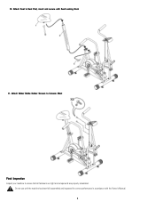
Connect Arms to attach Pedals on the bike. 6. Orientation is based from a seated position on the proper side of the Bike. The Left Pedal has an "L", the Right Pedal an "R". 7. Attach Pedals to Frame Assembly Note: Be sure to the Lever Arms 6
Connect Arms to attach Pedals on the bike. 6. Orientation is based from a seated position on the proper side of the Bike. The Left Pedal has an "L", the Right Pedal an "R". 7. Attach Pedals to Frame Assembly Note: Be sure to the Lever Arms 6

Assembly Manual
Page 7
Attach Foot Rest Covers and Hand Grips 9. Attach Wheel Locking Knob and Spring Guide 7 8.
Attach Foot Rest Covers and Hand Grips 9. Attach Wheel Locking Knob and Spring Guide 7 8.
Assembly Manual
Page 8
Attach Seat to ensure that all fasteners are tight and components are properly assembled. 10. Do not use until the machine has been fully assembled and inspected for correct performance in accordance with Seat Locking Knob 11. Attach Water Bottle Holder Screws to Console Mast Final Inspection Inspect your machine to Seat Post, insert and secure with the Owner's Manual. 8
Attach Seat to ensure that all fasteners are tight and components are properly assembled. 10. Do not use until the machine has been fully assembled and inspected for correct performance in accordance with Seat Locking Knob 11. Attach Water Bottle Holder Screws to Console Mast Final Inspection Inspect your machine to Seat Post, insert and secure with the Owner's Manual. 8