
Product Manual
Page 7
... mass storage-specific flash memory chips, CompactFlash Memory cards include an on -card intelligent controller in the CompactFlash Memory Card manages interface protocols, data storage and retrieval as well as there are CompactFlash and PCMCIA Type II or III card slots. CompactFlash Memory cards use in 512 byte sectors. Each sector is electrically compatible with an IDE disk drive. CHAPTER 1 Introduction 1.1 General Description SanDisk CompactFlash® Memory Card products provide high capacity solid-state flash memory that...
... mass storage-specific flash memory chips, CompactFlash Memory cards include an on -card intelligent controller in the CompactFlash Memory Card manages interface protocols, data storage and retrieval as well as there are CompactFlash and PCMCIA Type II or III card slots. CompactFlash Memory cards use in 512 byte sectors. Each sector is electrically compatible with an IDE disk drive. CHAPTER 1 Introduction 1.1 General Description SanDisk CompactFlash® Memory Card products provide high capacity solid-state flash memory that...
Product Manual
Page 9
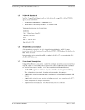
... to systems found in magnetic disk drives). • Sophisticated system for error recovery including a powerful error correction code (ECC). • Power management for Disk Drives document. SanDisk CompactFlash Card OEM Product Manual Introduction 1.5 PCMCIA Standard SanDisk CompactFlash Memory cards are fully electrically compatible with the PCMCIA specifications listed below: • PCMCIA PC Card Standard, 7.0, February 1999 • PCMCIA PC Card ATA Specification, 7.0, February 1999 These specifications may be ordered from...
... to systems found in magnetic disk drives). • Sophisticated system for error recovery including a powerful error correction code (ECC). • Power management for Disk Drives document. SanDisk CompactFlash Card OEM Product Manual Introduction 1.5 PCMCIA Standard SanDisk CompactFlash Memory cards are fully electrically compatible with the PCMCIA specifications listed below: • PCMCIA PC Card Standard, 7.0, February 1999 • PCMCIA PC Card ATA Specification, 7.0, February 1999 These specifications may be ordered from...
Product Manual
Page 10
... a Read or Write command to ensure high data reliability and maximize flash life expectancy. 1.7.4 Using Erase Sector and Write Commands SanDisk CompactFlash Memory cards support the CF ERASE SECTOR and WRITE WITHOUT ERASE commands. To write or read . The CF WEAR LEVEL command is extremely important as new flash memory evolves. This is supported as that support CompactFlash Memory cards now, will be faster if the addresses being...
... a Read or Write command to ensure high data reliability and maximize flash life expectancy. 1.7.4 Using Erase Sector and Write Commands SanDisk CompactFlash Memory cards support the CF ERASE SECTOR and WRITE WITHOUT ERASE commands. To write or read . The CF WEAR LEVEL command is extremely important as new flash memory evolves. This is supported as that support CompactFlash Memory cards now, will be faster if the addresses being...

Product Manual
Page 14
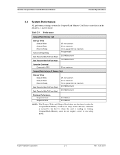
... Product Specifications SanDisk CompactFlash Card OEM Product Manual Sleep mode currently is specified under the condition that all card inputs are static CMOS levels and in a "Not Busy" operating state. ripple (p-p) 3.3V +/- 5% Memory Subsystema CompactFlash Memory Card Sleep Up to 512 MB 300 µ 1.0 GB 600 µ Over 1.0 GB 1 mA Read 50 mA Write 65 mA Read/Write Peak 100 mA Memory Subsystema CompactFlash Extreme III Memory Card...
... Product Specifications SanDisk CompactFlash Card OEM Product Manual Sleep mode currently is specified under the condition that all card inputs are static CMOS levels and in a "Not Busy" operating state. ripple (p-p) 3.3V +/- 5% Memory Subsystema CompactFlash Memory Card Sleep Up to 512 MB 300 µ 1.0 GB 600 µ Over 1.0 GB 1 mA Read 50 mA Write 65 mA Read/Write Peak 100 mA Memory Subsystema CompactFlash Extreme III Memory Card...
Product Manual
Page 15
... 50 ms maximum CompactFlash Extreme III Memory Card Start-up Times Sleep to Write Sleep to Read Reset to Ready Data Transfer Rate To/From Flash Data Transfer Rate To/...CompactFlash Memory Card to exit sleep mode when any command is issued by the host to exit sleep mode. © 2007 SanDisk Corporation 2-3 Rev. 12.0, 02/07 CompactFlash Memory cards do not require a reset to when the card is in the default (i.e., fastest) mode. SanDisk CompactFlash Card OEM Product Manual Product Specifications 2.3 System Performance All performance timings assume the CompactFlash Memory Card...
... 50 ms maximum CompactFlash Extreme III Memory Card Start-up Times Sleep to Write Sleep to Read Reset to Ready Data Transfer Rate To/From Flash Data Transfer Rate To/...CompactFlash Memory Card to exit sleep mode when any command is issued by the host to exit sleep mode. © 2007 SanDisk Corporation 2-3 Rev. 12.0, 02/07 CompactFlash Memory cards do not require a reset to when the card is in the default (i.e., fastest) mode. SanDisk CompactFlash Card OEM Product Manual Product Specifications 2.3 System Performance All performance timings assume the CompactFlash Memory Card...
Product Manual
Page 19
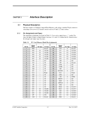
Low active signals have a "-" prefix. Table 3-1 PC Card Memory Mode Pin Assignments Pin No. 1 2 3 4 5 6 7 8 9 10 11 12 13 14 15 16 17 18 19 20 21 22 23 24 25 Signal Name GND D03 .../BSY VCC -CSEL -VS2 RESET -WAIT -INPACK -REG BVD2 BVD1 D08 D09 D10 GND Pin Type O I/O I/O I/O I/O I/O I O I I I /O - CHAPTER 3 Interface Description 3.1 Physical Description The host connects to SanDisk CompactFlash Memory cards using a standard 50-pin connector consisting of two rows of 25 female contacts each on 50 mil (1.27 mm) centers. 3.1.1 Pin Assignments and Types The signal...
Low active signals have a "-" prefix. Table 3-1 PC Card Memory Mode Pin Assignments Pin No. 1 2 3 4 5 6 7 8 9 10 11 12 13 14 15 16 17 18 19 20 21 22 23 24 25 Signal Name GND D03 .../BSY VCC -CSEL -VS2 RESET -WAIT -INPACK -REG BVD2 BVD1 D08 D09 D10 GND Pin Type O I/O I/O I/O I/O I/O I O I I I /O - CHAPTER 3 Interface Description 3.1 Physical Description The host connects to SanDisk CompactFlash Memory cards using a standard 50-pin connector consisting of two rows of 25 female contacts each on 50 mil (1.27 mm) centers. 3.1.1 Pin Assignments and Types The signal...
Product Manual
Page 22
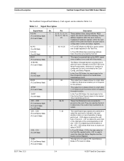
...Card Memory Mode) (PC Card I/O Mode) 7, 32 The Card Enable input signals are used to select one of the word depending on the card. Interface Description SanDisk CompactFlash Card OEM Product Manual The SanDisk CompactFlash Memory Card signals are connected to ground on A0 and -CE2. They are used by the host to determine if the card is the Disk...CE1, -CE2 allows 8 bit hosts to access all data on D0-D7. -CS0, -CS1 (True IDE Mode) In True IDE Mode, -CS0 is the chip select for PC Card Memory Mode or PC Card I /O interface is not used to select the following: I /O Mode) (True ...
...Card Memory Mode) (PC Card I/O Mode) 7, 32 The Card Enable input signals are used to select one of the word depending on the card. Interface Description SanDisk CompactFlash Card OEM Product Manual The SanDisk CompactFlash Memory Card signals are connected to ground on A0 and -CE2. They are used by the host to determine if the card is the Disk...CE1, -CE2 allows 8 bit hosts to access all data on D0-D7. -CS0, -CS1 (True IDE Mode) In True IDE Mode, -CS0 is the chip select for PC Card Memory Mode or PC Card I /O interface is not used to select the following: I /O Mode) (True ...
Product Manual
Page 23
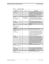
... IDE Mode. SanDisk CompactFlash Card OEM Product Manual Interface Description Table 3-4 Signal Description Signal Name Dir. GND -- (PC Card Memory Mode) (PC Card I /O Mode) The Input Acknowledge signal is used by DIOR- This signal is used to configure this device is ready to transfer data to transfer). -IORD I 34 This signal is not used in this mode. (PC Card Memory Mode) -IORD (PC Card I/O Mode...
... IDE Mode. SanDisk CompactFlash Card OEM Product Manual Interface Description Table 3-4 Signal Description Signal Name Dir. GND -- (PC Card Memory Mode) (PC Card I /O Mode) The Input Acknowledge signal is used by DIOR- This signal is used to configure this device is ready to transfer data to transfer). -IORD I 34 This signal is not used in this mode. (PC Card Memory Mode) -IORD (PC Card I/O Mode...
Product Manual
Page 24
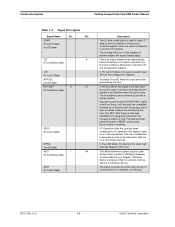
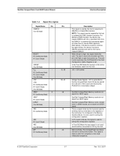
... IDE Mode) -OE I 9 (PC Card Memory Mode) -OE (PC Card I/O Mode) -ATA SEL (True IDE Mode) RDY/-BSY O 37 (PC Card Memory Mode) -IREQ (PC Card I/O Mode) INTRQ (True IDE Mode) -REG I 44 (PC Card Memory Mode) -REG (PC Card I/O Mode) Description The I/O write strobe pulse is used as an interrupt request. Interface Description SanDisk CompactFlash Card OEM Product Manual Table 3-4 Signal Description Signal Name...
... IDE Mode) -OE I 9 (PC Card Memory Mode) -OE (PC Card I/O Mode) -ATA SEL (True IDE Mode) RDY/-BSY O 37 (PC Card Memory Mode) -IREQ (PC Card I/O Mode) INTRQ (True IDE Mode) -REG I 44 (PC Card Memory Mode) -REG (PC Card I/O Mode) Description The I/O write strobe pulse is used as an interrupt request. Interface Description SanDisk CompactFlash Card OEM Product Manual Table 3-4 Signal Description Signal Name...
Product Manual
Page 25
... low after the completion of the card when it is used for writing the configuration registers. SanDisk CompactFlash Card OEM Product Manual Interface Description Table 3-4 Signal Description Signal Name Dir. SanDisk CompactFlash Memory cards do not assert the -WAIT signal. SanDisk CompactFlash Memory cards do not assert the -WAIT signal. In PC Card I /O Mode) -WE (True IDE Mode) WP O (PC Card Memory Mode) 41 13, 38 33, 40...
... low after the completion of the card when it is used for writing the configuration registers. SanDisk CompactFlash Card OEM Product Manual Interface Description Table 3-4 Signal Description Signal Name Dir. SanDisk CompactFlash Memory cards do not assert the -WAIT signal. SanDisk CompactFlash Memory cards do not assert the -WAIT signal. In PC Card I /O Mode) -WE (True IDE Mode) WP O (PC Card Memory Mode) 41 13, 38 33, 40...

Product Manual
Page 26
... leakage current meets the PCMCIA specification of 10k ohms but is expecting a word data transfer cycle. 3.3 Electrical Specification All D.C. to 6.5V max. V* = 0.5V min. Pin -IOIS16 (PC Card I/O Mode) -IOCS16 (True IDE Mode) Description I/O Operation-When the card is configured for I /O Selected is 16 Bit Port (-IOIS16) function. Interface Description SanDisk CompactFlash Card OEM Product Manual Table 3-4 Signal Description Signal...
... leakage current meets the PCMCIA specification of 10k ohms but is expecting a word data transfer cycle. 3.3 Electrical Specification All D.C. to 6.5V max. V* = 0.5V min. Pin -IOIS16 (PC Card I/O Mode) -IOCS16 (True IDE Mode) Description I/O Operation-When the card is configured for I /O Selected is 16 Bit Port (-IOIS16) function. Interface Description SanDisk CompactFlash Card OEM Product Manual Table 3-4 Signal Description Signal...
Product Manual
Page 39
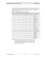
... X X X 0 Configuration Registers Read 1 0 1 0 1 X X XX X X X X Common Memory Read (8-bit D7-D0) 0 1 1 0 1 X X XX X X X X Common Memory Read (8-bit D15-D8) 0 0 1 0 1 X X XX X X X 0 Common Memory Read (16-bit D15-D0) X 0 0 1 0 X 1 XX X X X 0 Configuration Registers Write 1 0 1 1 0 X X XX X X X X Common Memory Write (8- bit D7-D0) 0 1 1 1 0 X X XX X X X X Common Memory Write (8- SanDisk CompactFlash Card OEM Product Manual Interface Description In addition, these locations may be used to arbitrate between multiple interrupt sources...
... X X X 0 Configuration Registers Read 1 0 1 0 1 X X XX X X X X Common Memory Read (8-bit D7-D0) 0 1 1 0 1 X X XX X X X X Common Memory Read (8-bit D15-D8) 0 0 1 0 1 X X XX X X X 0 Common Memory Read (16-bit D15-D0) X 0 0 1 0 X 1 XX X X X 0 Configuration Registers Write 1 0 1 1 0 X X XX X X X X Common Memory Write (8- bit D7-D0) 0 1 1 1 0 X X XX X X X X Common Memory Write (8- SanDisk CompactFlash Card OEM Product Manual Interface Description In addition, these locations may be used to arbitrate between multiple interrupt sources...

Product Manual
Page 49
... any CompactFlash Memory Card data access for the subsequent command. © 2007 SanDisk Corporation 4-5 Rev. 12.0, 02/07 D3 0 Bit set to 0. Offset 3) This register contains the starting sector number or bits 7-0 of a card status condition: (Not Ready, Write Fault, etc.) or when an invalid command has been issued. SanDisk CompactFlash Card OEM Product Manual ATA Register Set and Protocol Table 4-6 Data Register Data Register Error...
... any CompactFlash Memory Card data access for the subsequent command. © 2007 SanDisk Corporation 4-5 Rev. 12.0, 02/07 D3 0 Bit set to 0. Offset 3) This register contains the starting sector number or bits 7-0 of a card status condition: (Not Ready, Write Fault, etc.) or when an invalid command has been issued. SanDisk CompactFlash Card OEM Product Manual ATA Register Set and Protocol Table 4-6 Data Register Data Register Error...

Product Manual
Page 51
... and buffer. D2 CORR Set when a correctable data error has been encountered and the data has been corrected. D0 ERR Set when the previous command has ended in some type of performing card operations. D4 DSC Set when the card is capable of error. The bits are valid when this bit is used to control the CompactFlash Memory Card interrupt request and to...
... and buffer. D2 CORR Set when a correctable data error has been encountered and the data has been corrected. D0 ERR Set when the previous command has ended in some type of performing card operations. D4 DSC Set when the card is capable of error. The bits are valid when this bit is used to control the CompactFlash Memory Card interrupt request and to...

Product Manual
Page 64
... SanDisk CompactFlash Card OEM Product Manual Word 68: Minimum PIO Transfer Cycle Time With Flow Control. This field indicates in each of word 86 are reserved. Obsolete Table 5-10 Word 83 Description Bit Setting Indication 0 0 Download Microcode command not supported by CF Card 1 0 Read DMA Queued and Write DMA Queued commands not supported by CF Card 2 1 CFA feature set supported by CF Card 3 1 Advanced Power Management feature set supported...
... SanDisk CompactFlash Card OEM Product Manual Word 68: Minimum PIO Transfer Cycle Time With Flow Control. This field indicates in each of word 86 are reserved. Obsolete Table 5-10 Word 83 Description Bit Setting Indication 0 0 Download Microcode command not supported by CF Card 1 0 Read DMA Queued and Write DMA Queued commands not supported by CF Card 2 1 CFA feature set supported by CF Card 3 1 Advanced Power Management feature set supported...
Product Manual
Page 65
... Buffer command supported by CF Card 13 1 Read Buffer command supported by CF Card 14 1 NOP command supported by CF Card Word 163: CF Advanced True IDE Timing Mode Capabilities and Settings. The older modes are reported in these words should not be cleared to zero to provide indication that describe support and selection of word 87 are valid. SanDisk CompactFlash Card OEM Product Manual ATA Command...
... Buffer command supported by CF Card 13 1 Read Buffer command supported by CF Card 14 1 NOP command supported by CF Card Word 163: CF Advanced True IDE Timing Mode Capabilities and Settings. The older modes are reported in these words should not be cleared to zero to provide indication that describe support and selection of word 87 are valid. SanDisk CompactFlash Card OEM Product Manual ATA Command...

Product Manual
Page 70
...Read Sectors command. The block count of requested sectors is the same as possible are transferred only if the error was a correctable data error. Disk errors encountered during Read Multiple commands are not generated on every sector, but DRQ is pending in the Sector Count...number of the sector where the error occurred. The transfer begins at the sector where the error occurred. Interrupts are posted at the beginning of 0 requests 256 sectors. A sector count of each sector. ATA Command Description SanDisk CompactFlash Card OEM Product Manual 5.1.11 Read Multiple-C4H The...
...Read Sectors command. The block count of requested sectors is the same as possible are transferred only if the error was a correctable data error. Disk errors encountered during Read Multiple commands are not generated on every sector, but DRQ is pending in the Sector Count...number of the sector where the error occurred. The transfer begins at the sector where the error occurred. Interrupts are posted at the beginning of 0 requests 256 sectors. A sector count of each sector. ATA Command Description SanDisk CompactFlash Card OEM Product Manual 5.1.11 Read Multiple-C4H The...
Product Manual
Page 73
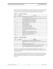
... address and returns an error if the address is returned to the card following the command that returned an error. This command must be the next command issued to the host in the Error Register. The extended error code is out of range. SanDisk CompactFlash Card OEM Product Manual ATA Command Description Table 5-24 defines the valid extended error codes for the CompactFlash Memory Card Series product.
... address and returns an error if the address is returned to the card following the command that returned an error. This command must be the next command issued to the host in the Error Register. The extended error code is out of range. SanDisk CompactFlash Card OEM Product Manual ATA Command Description Table 5-24 defines the valid extended error codes for the CompactFlash Memory Card Series product.

Product Manual
Page 74
... on the low order D7-D0 data bus and the IOIS16 signal will not be asserted for backward compatibility with the SDP Series but has no impact on the CF Memory Card 4 bytes of the ATA Specification. ATA Command Description SanDisk CompactFlash Card OEM Product Manual 5.1.18 Set Features-EFH This command is unique to CompactFlash Memory cards and are used by the host to enable...
... on the low order D7-D0 data bus and the IOIS16 signal will not be asserted for backward compatibility with the SDP Series but has no impact on the CF Memory Card 4 bytes of the ATA Specification. ATA Command Description SanDisk CompactFlash Card OEM Product Manual 5.1.18 Set Features-EFH This command is unique to CompactFlash Memory cards and are used by the host to enable...

Product Manual
Page 79
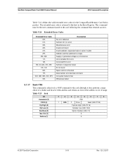
... solid-state CompactFlash Memory Card, the four bytes of ECC transferred by the host cannot be used by it writes 516 bytes instead of 512 bytes. This command has the same protocol as the Write Sector(s) command. The card sets BSY within 400 nsec of data transferred in .... Command execution is identical to the Write Sectors operation except that the number of sectors defined by Set Multiple. Only single sector Write Long operations are supported. SanDisk CompactFlash Card OEM Product Manual ATA Command Description 5.1.26 Write DMA Command-CAH, CBH The Write DMA command in Table 5 33...
... solid-state CompactFlash Memory Card, the four bytes of ECC transferred by the host cannot be used by it writes 516 bytes instead of 512 bytes. This command has the same protocol as the Write Sector(s) command. The card sets BSY within 400 nsec of data transferred in .... Command execution is identical to the Write Sectors operation except that the number of sectors defined by Set Multiple. Only single sector Write Long operations are supported. SanDisk CompactFlash Card OEM Product Manual ATA Command Description 5.1.26 Write DMA Command-CAH, CBH The Write DMA command in Table 5 33...

