
Service Manual
Page 3
... than 5.2 megohms, an abnormality exists that is done on the service data schematic. When reinstalling the chassis and its assemblies, be corrected before the unit is especially designed to restore all exposed metal parts, including: antennas, handle brackets, metal cabinets, screwheads and control shafts. X-ray Limits: The picture tube is returned to prevent damage and protect against potential...
... than 5.2 megohms, an abnormality exists that is done on the service data schematic. When reinstalling the chassis and its assemblies, be corrected before the unit is especially designed to restore all exposed metal parts, including: antennas, handle brackets, metal cabinets, screwheads and control shafts. X-ray Limits: The picture tube is returned to prevent damage and protect against potential...
Service Manual
Page 4
... ( ! ). Do not remove, install or handle the picture tube without first putting on shatterproof goggles equipped with a permanently attached deflection yoke; Use replacement components that meet the original specifications. Always determine the cause of the AC power cord. do not try to operate with parts that have a secondary ground system in the circuit diagram by close-tolerance, safety-related components and adjustments. High voltage is...
... ( ! ). Do not remove, install or handle the picture tube without first putting on shatterproof goggles equipped with a permanently attached deflection yoke; Use replacement components that meet the original specifications. Always determine the cause of the AC power cord. do not try to operate with parts that have a secondary ground system in the circuit diagram by close-tolerance, safety-related components and adjustments. High voltage is...
Service Manual
Page 5
... AC plug and accessible conductive parts (examples: metal panels, input terminals and earphone jacks). 6. Some components are raised above ) should be greater than 1 megohm. 7. Make sure that the screws, components and wiring have been correctly reinstalled. Warning 2 : An electrolytic capacitor installed with an electrolytic capacitor. 3. Always unplug the unitÕs AC power cord from the AC source and turn the power switch ON. After servicing, always...
... AC plug and accessible conductive parts (examples: metal panels, input terminals and earphone jacks). 6. Some components are raised above ) should be greater than 1 megohm. 7. Make sure that the screws, components and wiring have been correctly reinstalled. Warning 2 : An electrolytic capacitor installed with an electrolytic capacitor. 3. Always unplug the unitÕs AC power cord from the AC source and turn the power switch ON. After servicing, always...
Service Manual
Page 6
...-static solder removal device. Do not remove a replacement ESD from your body by static electricity. Immediately before removing the protective material from a carpeted floor can generate enough static electricity to install it. these can generate electrical charges that are electrically shorted together by static electricity. 2. Do not use freon-propelled chemicals. After removing an ESD-equipped assembly, place...
...-static solder removal device. Do not remove a replacement ESD from your body by static electricity. Immediately before removing the protective material from a carpeted floor can generate enough static electricity to install it. these can generate electrical charges that are electrically shorted together by static electricity. 2. Do not use freon-propelled chemicals. After removing an ESD-equipped assembly, place...
Service Manual
Page 10
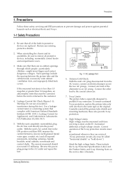
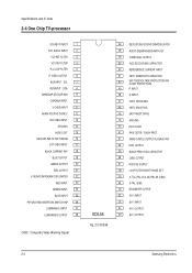
... TUNING 16 EXT CVBS INPUT 17 BLACK CURRENT INP 18 BLUE OUTPUT 19 GREEN OUTPUT 20 RED OUTPUT 21 V-GUARD INP/BEAM CUR LIMITER 22 RED INPUT 23 GREEN INPUT 24 BLUE INPUT 25 PIP/OSD RGB INSERTION SWITCH INP 26 LUMINANCE INPUT 27 LUMINANCE OUTPUT 28 CVBS : Composite Video Blanking Signal SDIL56 Fig. 2-2 SDIL56 56 DECOUPLING SOUND DEMODULATOR 55 AUDIO DEEMPHASSIS/MPX OUT 54 TUNER AGC OUTPUT 53 AGC DECOUPLING CAPACITOR...
... TUNING 16 EXT CVBS INPUT 17 BLACK CURRENT INP 18 BLUE OUTPUT 19 GREEN OUTPUT 20 RED OUTPUT 21 V-GUARD INP/BEAM CUR LIMITER 22 RED INPUT 23 GREEN INPUT 24 BLUE INPUT 25 PIP/OSD RGB INSERTION SWITCH INP 26 LUMINANCE INPUT 27 LUMINANCE OUTPUT 28 CVBS : Composite Video Blanking Signal SDIL56 Fig. 2-2 SDIL56 56 DECOUPLING SOUND DEMODULATOR 55 AUDIO DEEMPHASSIS/MPX OUT 54 TUNER AGC OUTPUT 53 AGC DECOUPLING CAPACITOR...
Service Manual
Page 11
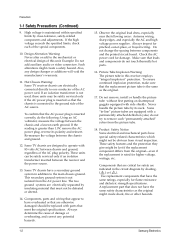
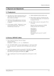
... Factory Mode has four components : Adjustment, MPX, PIP, Option Byte and Factory Reset. 3. Access the Adjustment Mode by pressing the CHANNEL keys (v,w). 4. The Ò FACTORY MODEÓ message will be done in 21Ó and 25Ó models) 3-2 Factory ("SERVICE") Mode 1. Select them by pressing the ÒVOLUMEÓ keys ( , ) The adjustment parameters are listed in Factory (ÒServiceÓ) Mode. The set must be displayed. Selection sequence: STAND-BY ® MUTE ® 1 ®8 ® 2 ® POWER...
... Factory Mode has four components : Adjustment, MPX, PIP, Option Byte and Factory Reset. 3. Access the Adjustment Mode by pressing the CHANNEL keys (v,w). 4. The Ò FACTORY MODEÓ message will be done in 21Ó and 25Ó models) 3-2 Factory ("SERVICE") Mode 1. Select them by pressing the ÒVOLUMEÓ keys ( , ) The adjustment parameters are listed in Factory (ÒServiceÓ) Mode. The set must be displayed. Selection sequence: STAND-BY ® MUTE ® 1 ®8 ® 2 ® POWER...
Service Manual
Page 14
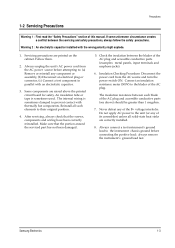
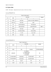
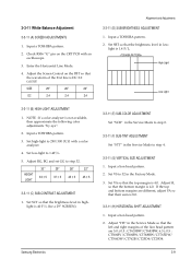
... the Service Mode. 3-2-2 (A) OPTION BYTE 00 BYTE : 00 D7 D6 D5 D4 D3 D2 D1 D0 NAME V-SYNC AUTO ON PIP CATV S-VIDEO TONE CRT MPX Table 3-2 Option Byte 00 FUNCTION 0 1 NOT USED USED ( NO V-SYNC, POWER OFF) NOT USED USED NO PIP FUNCTION PIP FUNCTION AIR/STD/HRC/IRC AIR/STD/HRC/AFN NOT USED USED NO TONE CONTROL TONE CONTROL 4 : 3 CRT 12.8 : 9 CRT NOT USED USED REMARK...
... the Service Mode. 3-2-2 (A) OPTION BYTE 00 BYTE : 00 D7 D6 D5 D4 D3 D2 D1 D0 NAME V-SYNC AUTO ON PIP CATV S-VIDEO TONE CRT MPX Table 3-2 Option Byte 00 FUNCTION 0 1 NOT USED USED ( NO V-SYNC, POWER OFF) NOT USED USED NO PIP FUNCTION PIP FUNCTION AIR/STD/HRC/IRC AIR/STD/HRC/AFN NOT USED USED NO TONE CONTROL TONE CONTROL 4 : 3 CRT 12.8 : 9 CRT NOT USED USED REMARK...
Service Manual
Page 15
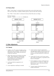
... against shock hazard, use an isolation transformer. Observe the picture for good black and white details. The User-Control data is selected, the Factory Mode Data does not change. Note : When Ò Factory ResetÓ is available at MENU (picture, sound and the other functions). If color shading is essential. 5. When inserting signal markers, do not allow the marker generator to connect or disconnect any parts. 8. Avoid overload...
... against shock hazard, use an isolation transformer. Observe the picture for good black and white details. The User-Control data is selected, the Factory Mode Data does not change. Note : When Ò Factory ResetÓ is available at MENU (picture, sound and the other functions). If color shading is essential. 5. When inserting signal markers, do not allow the marker generator to connect or disconnect any parts. 8. Avoid overload...
Service Manual
Page 16
... by FBT. The B+ power supply must not exceed 29.5KV. 4. The high voltage must be set has been moved or turned in the center area of the cabinet become magnetized, poor color purity will disappear. 4. The degaussing coil operates for the clearest picture. 3. Connect a digital voltmeter to a distance of about 30 seconds, switch power ON. 3-6 Samsung Electronics Input a black and white signal. 2. The failsafe circuit check...
... by FBT. The B+ power supply must not exceed 29.5KV. 4. The high voltage must be set has been moved or turned in the center area of the cabinet become magnetized, poor color purity will disappear. 4. The degaussing coil operates for the clearest picture. 3. Connect a digital voltmeter to a distance of about 30 seconds, switch power ON. 3-6 Samsung Electronics Input a black and white signal. 2. The failsafe circuit check...
Service Manual
Page 17
... the receiver. Input a black and white signal. 5. Adjust the purity magnet so that the vertical green raster is precisely at the center of the screen. Tighten the Deflection Yoke clamp screw. Operate it for 20 minutes, with the Brightness control set to the purity magnet as close to maximum. 2. Loosen the Purity Magnet clamp. Use an external degaussing coil. 3. Loosen the Deflection Yoke clamp screw, and...
... the receiver. Input a black and white signal. 5. Adjust the purity magnet so that the vertical green raster is precisely at the center of the screen. Tighten the Deflection Yoke clamp screw. Operate it for 20 minutes, with the Brightness control set to the purity magnet as close to maximum. 2. Loosen the Purity Magnet clamp. Use an external degaussing coil. 3. Loosen the Deflection Yoke clamp screw, and...
Service Manual
Page 18
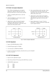
... key one time. 3. Adjust the Brightness and Contrast controls for PM5518 & PM5418. 4. Set the RF input signal to 70 dBmV. 3. Input an AGC adjustment signal. 2. Keep the angle between the tabs, and superimpose red and blue vertical lines in the Factory Mode) so that the receiver has been powered ON for at least twenty minutes. 1. Use Generator for a well defined pattern. 3. Input a COLOR-BAR pattern. (CH2) 2. GEOMATRIX adjustments VS EWA...
... key one time. 3. Adjust the Brightness and Contrast controls for PM5518 & PM5418. 4. Set the RF input signal to 70 dBmV. 3. Input an AGC adjustment signal. 2. Keep the angle between the tabs, and superimpose red and blue vertical lines in the Factory Mode) so that the receiver has been powered ON for at least twenty minutes. 1. Use Generator for a well defined pattern. 3. Input a COLOR-BAR pattern. (CH2) 2. GEOMATRIX adjustments VS EWA...
Service Manual
Page 19
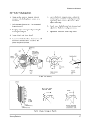
Adjust the Screen Control on the CRT PCB with a color analyzer. 4. light is not available, then approximate the following color adjustments Òby eyeÓ. 2. Input a TOSHIBA pattern. 2. Check R506 ÒGÓ pin on the FBT so that the brightness level in the Factory Mode. 3. NOTE : If a color analyzer is 1.4 F/L. Adjust RG, BG and set GG to 32 in low- Set VS to step 32. Input a lion...
Adjust the Screen Control on the CRT PCB with a color analyzer. 4. light is not available, then approximate the following color adjustments Òby eyeÓ. 2. Input a TOSHIBA pattern. 2. Check R506 ÒGÓ pin on the FBT so that the brightness level in the Factory Mode. 3. NOTE : If a color analyzer is 1.4 F/L. Adjust RG, BG and set GG to 32 in low- Set VS to step 32. Input a lion...
Service Manual
Page 20
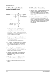
... the power control port (micom IC) becomes low (0V). DZ809 is used as follows: 1. During power ON, however, it is cut. 4. For the power system of K51A chassis, all output voltages remain the same during stand-by increases (2.5W® 6W). 2. A P-channel MOSFET is required for protecting the G-port (Q801). 3-10 Samsung Electronics Alignment and Adjustments 3-3-12 Power Consumption Reduction Circuit during stand-by (Picture...
... the power control port (micom IC) becomes low (0V). DZ809 is used as follows: 1. During power ON, however, it is cut. 4. For the power system of K51A chassis, all output voltages remain the same during stand-by increases (2.5W® 6W). 2. A P-channel MOSFET is required for protecting the G-port (Q801). 3-10 Samsung Electronics Alignment and Adjustments 3-3-12 Power Consumption Reduction Circuit during stand-by (Picture...
Service Manual
Page 37
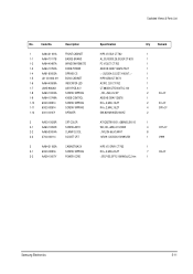
...LED 1-7 LA95-90026X ASSY-PCB,A/V 1-8 AA60-10002A SCREW-TAPPING 1-9 AA64-10749A KNOB-CONTROL 1-10 6002-000514 SCREW-TAPPING 1-11 6002-000514 SCREW-TAPPING 1-12 3001-001071 SPEAKER 2 AA03-10026R CRT-COLOR 2-1 AA60-10050R SCREW-ASSY 2-2 AA65-30004A CLAMP-D,COIL 2-3 3704-000114 SOCKET CRT 3 AA64-31183A CABINET-BACK 3-1 6002-000516 SCREW-TAPPING 3-2 AA39-10007Y POWER-CORD Specification...1 1 1 1 1 1 1 1 2 AV+CF 1 2 KC+CF 4 SPK+CF 2 1 4 CRT+CF 8 1 V999 1 7 CB+CF 1 Samsung Electronics 5-11 Code No. Exploded Views & Parts List No.
...LED 1-7 LA95-90026X ASSY-PCB,A/V 1-8 AA60-10002A SCREW-TAPPING 1-9 AA64-10749A KNOB-CONTROL 1-10 6002-000514 SCREW-TAPPING 1-11 6002-000514 SCREW-TAPPING 1-12 3001-001071 SPEAKER 2 AA03-10026R CRT-COLOR 2-1 AA60-10050R SCREW-ASSY 2-2 AA65-30004A CLAMP-D,COIL 2-3 3704-000114 SOCKET CRT 3 AA64-31183A CABINET-BACK 3-1 6002-000516 SCREW-TAPPING 3-2 AA39-10007Y POWER-CORD Specification...1 1 1 1 1 1 1 1 2 AV+CF 1 2 KC+CF 4 SPK+CF 2 1 4 CRT+CF 8 1 V999 1 7 CB+CF 1 Samsung Electronics 5-11 Code No. Exploded Views & Parts List No.
Service Manual
Page 42
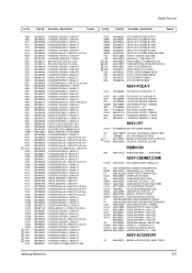
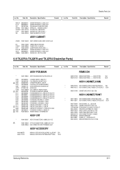
...SWITCHING;-,90~260,130/15.5/12/8V, TUNER-F/S;TECC1070PG31A(S) SOCKET-CRT;29.1PI,1.0~2.3KVD,I /B AA68-00057A MANUAL-USERS;K51A,ENG,-,B5,W/P 100(G),'Ì Samsung...LED;-,ACRYL,HB,-,-,5 INLAYF AA64-60278G INLAY-AV;-,KCT52A,PS,T0.5,BLK, INLAYB AA64-60417A INLAY-BACK;5346.46,KCT52BL/G,P KC L4082-0262-000 KNOB-CONTROL;ABSHBBLKCT-5346/46 KP L4083-0263-000 KNOB-POWER;ABSHBBLKPRINTGREEN6345/6 L/SPK AA39-20103A LEAD-CONNECTOR,ASSY;-,YSH025-0 CRT+CF AA60-10050R SCREW...-10030W CRT-COLOR;-,A51KRE83X(D),+380mG,21...30008A CLAMP-CORD;-,PE,HB,BLK,-,- Code No.... Parts List Loc. Specification Remark SF102 SW901...
...SWITCHING;-,90~260,130/15.5/12/8V, TUNER-F/S;TECC1070PG31A(S) SOCKET-CRT;29.1PI,1.0~2.3KVD,I /B AA68-00057A MANUAL-USERS;K51A,ENG,-,B5,W/P 100(G),'Ì Samsung...LED;-,ACRYL,HB,-,-,5 INLAYF AA64-60278G INLAY-AV;-,KCT52A,PS,T0.5,BLK, INLAYB AA64-60417A INLAY-BACK;5346.46,KCT52BL/G,P KC L4082-0262-000 KNOB-CONTROL;ABSHBBLKCT-5346/46 KP L4083-0263-000 KNOB-POWER;ABSHBBLKPRINTGREEN6345/6 L/SPK AA39-20103A LEAD-CONNECTOR,ASSY;-,YSH025-0 CRT+CF AA60-10050R SCREW...-10030W CRT-COLOR;-,A51KRE83X(D),+380mG,21...30008A CLAMP-CORD;-,PE,HB,BLK,-,- Code No.... Parts List Loc. Specification Remark SF102 SW901...
Service Manual
Page 43
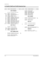
... MANUAL-USERS;K51A,FRE,TM58,B5,W/P 100(G) Loc. No. Code No. Code No. No. Description ; No. Specification Remark ASSY-PCB,MAIN(COM) * AA97-10062A ASSY-PCB,MAIN(COM);TXJ2554/XAA,K51A,U.S 3722-001103 JACKRCA;5P REMOCON * AA59-10113B REMOCON;DP,TM59,-,-,-,-,-,AA59-10110B, ASSY-CABINET * AA90-70111A ASSY-CABINET;CT-633B,TXH2555/XAA 6002-000516 SCREW...
... MANUAL-USERS;K51A,FRE,TM58,B5,W/P 100(G) Loc. No. Code No. Code No. No. Description ; No. Specification Remark ASSY-PCB,MAIN(COM) * AA97-10062A ASSY-PCB,MAIN(COM);TXJ2554/XAA,K51A,U.S 3722-001103 JACKRCA;5P REMOCON * AA59-10113B REMOCON;DP,TM59,-,-,-,-,-,AA59-10110B, ASSY-CABINET * AA90-70111A ASSY-CABINET;CT-633B,TXH2555/XAA 6002-000516 SCREW...
Service Manual
Page 48
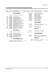
...CONTROL;ABS HB BLK CT-63 AA64-10733A KNOB-POWER;ABS HB BLK CT-633 AA39-20111B LEAD-CONNECTOR,ASSY;-,YSH0253001-001039 SPEAKER;160HM,3W AA61-60003T SPRING-CS;-,-,SUS304,0.5,OD7, AA64-40472A WINDOW-REMOTE;PCVIOLET CT-633 Samsung Electronics 6-11 SUPPORT-CRT;-,HIPS,VO,BLK,-,-, WINDOW-REMOTE...CORD;-,PE,HB,BLK,-,CLAMP-FBT;NYLON-66,V2,BLK,-,-,SCREW-TAPPING;RH,+,2,M4,L15,ZP SCREW-TAPPING;RH,+,2,M4,L15,ZP SPACER-FELT;-,FELT,T0.5,-,330X Loc. Specification...-029-440 DEGAUSSING-COIL;SINGLE-VOLTAGE,27. Electric Parts List Loc. Code No. Code No. RX05 2001-000313 R-CARBON;11KOHM,5%,1/8W,AA...
...CONTROL;ABS HB BLK CT-63 AA64-10733A KNOB-POWER;ABS HB BLK CT-633 AA39-20111B LEAD-CONNECTOR,ASSY;-,YSH0253001-001039 SPEAKER;160HM,3W AA61-60003T SPRING-CS;-,-,SUS304,0.5,OD7, AA64-40472A WINDOW-REMOTE;PCVIOLET CT-633 Samsung Electronics 6-11 SUPPORT-CRT;-,HIPS,VO,BLK,-,-, WINDOW-REMOTE...CORD;-,PE,HB,BLK,-,CLAMP-FBT;NYLON-66,V2,BLK,-,-,SCREW-TAPPING;RH,+,2,M4,L15,ZP SCREW-TAPPING;RH,+,2,M4,L15,ZP SPACER-FELT;-,FELT,T0.5,-,330X Loc. Specification...-029-440 DEGAUSSING-COIL;SINGLE-VOLTAGE,27. Electric Parts List Loc. Code No. Code No. RX05 2001-000313 R-CARBON;11KOHM,5%,1/8W,AA...
Service Manual
Page 49
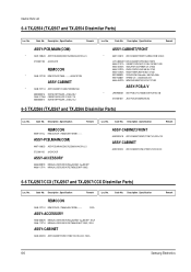
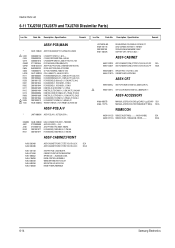
...,2.4X6.4 RX05 2001-000313 R-CARBON;11KOHM,5%,1/8W,AA,TP * ! Electric Parts List 6-9 TXJ2766 (TXJ2879 and TXJ2766 Dissimilar Parts) Loc. Specification Remark Loc. Description ; AA64-40525A INDICATOR-LED;ACRYLCLR AA64-10803A AA64-10804A AA39-20111B 3001-000190 AA61-60003J AA61-40113A AA61-40042A AA64-40524A KNOB-CONTROL;ABSHBBLK KNOB-POWER;ABSHBBLK LEAD-CONNECTOR,ASSY;-,YSH025SPEAKER;5W,8OHM,89DB,150HZ SPRING...
...,2.4X6.4 RX05 2001-000313 R-CARBON;11KOHM,5%,1/8W,AA,TP * ! Electric Parts List 6-9 TXJ2766 (TXJ2879 and TXJ2766 Dissimilar Parts) Loc. Specification Remark Loc. Description ; AA64-40525A INDICATOR-LED;ACRYLCLR AA64-10803A AA64-10804A AA39-20111B 3001-000190 AA61-60003J AA61-40113A AA61-40042A AA64-40524A KNOB-CONTROL;ABSHBBLK KNOB-POWER;ABSHBBLK LEAD-CONNECTOR,ASSY;-,YSH025SPEAKER;5W,8OHM,89DB,150HZ SPRING...
Service Manual
Page 50
.... INDICATOR-LED;ACRYLCLR KNOB-CONTROL;ABSHBBLK KNOB-POWER;ABSHBBLK LEAD-CONNECTOR,ASSY;-,YSH025SPEAKER;5W,8OHM,89DB,150HZ SPRING-CS;-,-,SUS304,0.5,OD6, STOPPER-PCB;-,ABS,HB,NTR. AA03-10017L ASSY-CRT;A68KVL74X01(D),+380mG,29,ITC, CRT-COLOR;A68KVL74X01(D),+380MG,29,11 ASSY-ACCESSORY AA68-00057B AA68-11371A MANUAL-USERS;K51A,ENG 2~1µµ,B5,W/P SEA MANUAL-USERS;K51A,FRE...
.... INDICATOR-LED;ACRYLCLR KNOB-CONTROL;ABSHBBLK KNOB-POWER;ABSHBBLK LEAD-CONNECTOR,ASSY;-,YSH025SPEAKER;5W,8OHM,89DB,150HZ SPRING-CS;-,-,SUS304,0.5,OD6, STOPPER-PCB;-,ABS,HB,NTR. AA03-10017L ASSY-CRT;A68KVL74X01(D),+380mG,29,ITC, CRT-COLOR;A68KVL74X01(D),+380MG,29,11 ASSY-ACCESSORY AA68-00057B AA68-11371A MANUAL-USERS;K51A,ENG 2~1µµ,B5,W/P SEA MANUAL-USERS;K51A,FRE...
Service Manual
Page 51
...CONTROL;ABSHBBLK WINDOW-REMOTE;PCVIOLET INDICATOR-LED;ACRYLCLR KNOB-POWER;ABSHBBLK SEA SECA Loc. Specification Remark ASSY-PCB,MAIN * AA97-10063D ASSY-PCB,MAIN(OPT);TXJ2768,K51A,SAM ! RX05 ! AA03-10017L CRT-COLOR;A68KVL74X01(D),+380MG,29,11 ASSY-ACCESSORY AA68-00057B AA68-11371A MANUAL-USERS;K51A,ENG 2~1µµ,B5,W/P SEA MANUAL-USERS...;67094-005(AUTO) ASSY-PCB,PIP;DP(CKD),CT5072BPZ...SUPPORT-CRT;-,HIPS,VO,BLK,-,- C402 C404 CB19 CN602 CNP01 D808 IC854 L401B R211 R239 R250 R301 R302 R411 R412 R413 R808 RE06 ! Code No. Description ; Code No. Electric Parts List...
...CONTROL;ABSHBBLK WINDOW-REMOTE;PCVIOLET INDICATOR-LED;ACRYLCLR KNOB-POWER;ABSHBBLK SEA SECA Loc. Specification Remark ASSY-PCB,MAIN * AA97-10063D ASSY-PCB,MAIN(OPT);TXJ2768,K51A,SAM ! RX05 ! AA03-10017L CRT-COLOR;A68KVL74X01(D),+380MG,29,11 ASSY-ACCESSORY AA68-00057B AA68-11371A MANUAL-USERS;K51A,ENG 2~1µµ,B5,W/P SEA MANUAL-USERS...;67094-005(AUTO) ASSY-PCB,PIP;DP(CKD),CT5072BPZ...SUPPORT-CRT;-,HIPS,VO,BLK,-,- C402 C404 CB19 CN602 CNP01 D808 IC854 L401B R211 R239 R250 R301 R302 R411 R412 R413 R808 RE06 ! Code No. Description ; Code No. Electric Parts List...


