User Manual
Page 3
... can be selected by one or more of the following measures: - Reorient or relocate the receiving antenna. - Introduction The STP-103 and STP-103P Roll Printer are as specified in a particular installation. Different print densities can radiate radio frequency energy and, if not ...can radiate radio frequency energy and, if not installed and uses in a commercial environment. Warning - RS-232 serial interface (STP-103S), Parallel interface (STP-103P). 4. However, there is no guarantee that to which case the user will not occur in the Canadian department of the...
... can be selected by one or more of the following measures: - Reorient or relocate the receiving antenna. - Introduction The STP-103 and STP-103P Roll Printer are as specified in a particular installation. Different print densities can radiate radio frequency energy and, if not ...can radiate radio frequency energy and, if not installed and uses in a commercial environment. Warning - RS-232 serial interface (STP-103S), Parallel interface (STP-103P). 4. However, there is no guarantee that to which case the user will not occur in the Canadian department of the...
User Manual
Page 4
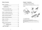
Connecting the cable 10 2-1. Setting the DIP Switching 14 Chapter 5. Parallel Type (STP-103P 51 APPENDIX B - Checking the contents of the Printer The items illustrated below are damaged or missing, please contact your printer....with your dealer for the printer. Table of the Printer 7 1-2. Running the Self Test 16 Chapter 6. Serial Type (STP-103S 51 - Locating the Printer 7 1-3. Code Table 18 Chapter 8. Specification 52 ※Option : STP-103DK 53 6 Chapter 1. Unpacking 7 1-1. Operating Control Panel 9 Chapter 2. Installing the Paper Roll 13 Chapter 4. ...
Connecting the cable 10 2-1. Setting the DIP Switching 14 Chapter 5. Parallel Type (STP-103P 51 APPENDIX B - Checking the contents of the Printer The items illustrated below are damaged or missing, please contact your printer....with your dealer for the printer. Table of the Printer 7 1-2. Running the Self Test 16 Chapter 6. Serial Type (STP-103S 51 - Locating the Printer 7 1-3. Code Table 18 Chapter 8. Specification 52 ※Option : STP-103DK 53 6 Chapter 1. Unpacking 7 1-1. Operating Control Panel 9 Chapter 2. Installing the Paper Roll 13 Chapter 4. ...
User Manual
Page 7
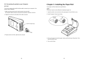
... printer and computer are turned off before installing the paper roll. 1. Tighten the screws on the Printer. 12 13 Connecting the printer to your Computer STP-103P You need an appropriate parallel interface cable to connect your computer to the printer's built-in interface. 1.
... printer and computer are turned off before installing the paper roll. 1. Tighten the screws on the Printer. 12 13 Connecting the printer to your Computer STP-103P You need an appropriate parallel interface cable to connect your computer to the printer's built-in interface. 1.
User Manual
Page 26
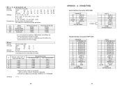
...m selects the mode, as follows: CODE39, ITF, CODABAR [Default] n = 3 50 APPENDIX A : CONNECTORS Serial Interface Connector (STP-103S) PRINTER 20 TXD (O) 19 RXD (I) 21 CTS (I) 22~25 GND 18 RTS (O) FGND 25 PINE MALE CONNECT HOST ...2 RXD (I) 3 TXD (O) 7 RTS (O) 5 GND 8 CTS (I) 4 DTR (O) 6 DSR (I) FGND 9 PINE FEMALE Parallel Interface Connector (STP-103P) PRINTER 1 /STROBE (I/O) 2 DATA0 (I/O) 3 DATA1 (I/O) 4 DATA2 (I/O) 5 DATA3 (I/O) 6 DATA4 (I/O) 7 DATA5 (I/O) 8 DATA6 (I/O) 9 DATA7 (I/O) 10 ...
...m selects the mode, as follows: CODE39, ITF, CODABAR [Default] n = 3 50 APPENDIX A : CONNECTORS Serial Interface Connector (STP-103S) PRINTER 20 TXD (O) 19 RXD (I) 21 CTS (I) 22~25 GND 18 RTS (O) FGND 25 PINE MALE CONNECT HOST ...2 RXD (I) 3 TXD (O) 7 RTS (O) 5 GND 8 CTS (I) 4 DTR (O) 6 DSR (I) FGND 9 PINE FEMALE Parallel Interface Connector (STP-103P) PRINTER 1 /STROBE (I/O) 2 DATA0 (I/O) 3 DATA1 (I/O) 4 DATA2 (I/O) 5 DATA3 (I/O) 6 DATA4 (I/O) 7 DATA5 (I/O) 8 DATA6 (I/O) 9 DATA7 (I/O) 10 ...

User Manual
Page 28
... pin m as follows : m=0 Connector pin : Drawer kick-out connector pin 2. [Details] The pulse ON time is [t1*2ms] and the OFF time is [t2*2ms]. 2) Parallel Interface Connector Specification PRINTER 1 /STROBE (I/O) 2 DATA0 (I/O) 3 DATA1 (I/O) 4 DATA2 (I/O) 5 DATA3 (I/O) 6 DATA4 (I/O) 7 DATA5 (I/O) 8 DATA6 (I/O) 9 DATA7 (I/O) 10 /ACK (I) 11 BUSY (I) 12 PE (I) 13 SLCT 15 /ERROR (I) 22~25...
... pin m as follows : m=0 Connector pin : Drawer kick-out connector pin 2. [Details] The pulse ON time is [t1*2ms] and the OFF time is [t2*2ms]. 2) Parallel Interface Connector Specification PRINTER 1 /STROBE (I/O) 2 DATA0 (I/O) 3 DATA1 (I/O) 4 DATA2 (I/O) 5 DATA3 (I/O) 6 DATA4 (I/O) 7 DATA5 (I/O) 8 DATA6 (I/O) 9 DATA7 (I/O) 10 /ACK (I) 11 BUSY (I) 12 PE (I) 13 SLCT 15 /ERROR (I) 22~25...