
User Manual (ENGLISH)
Page 2
Preparation Table of Contents Table of Contents Preparation Features and Design 4 Caution on Lamp Use and Replacement 5 Projector and Accessories Front/Upper Side and Accessories 8 Rear Side and Cables 10 Remote Control Buttons 11 Operating the Remote Control 12 Installation and Basic Adjustments ...
Preparation Table of Contents Table of Contents Preparation Features and Design 4 Caution on Lamp Use and Replacement 5 Projector and Accessories Front/Upper Side and Accessories 8 Rear Side and Cables 10 Remote Control Buttons 11 Operating the Remote Control 12 Installation and Basic Adjustments ...
User Manual (ENGLISH)
Page 5
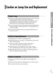
... be careful not to explode.) I Free servicing will be offered within 300 hours of product use time by glass pieces. I The Projector lamp changes in nature depending on time of the lamp, it is possible to be very hot. Preparation Caution on Lamp Use and Replacement Caution...not stare light source directly. Refer to the manual for replacement. (Ultra violets from the lamp can damage your dealer to a defective lamp. I This projector produces intense light. I Turn off . I Contact your eyes.) I You can be hurt by pressing the INFO button on the remote control. It ...
... be careful not to explode.) I Free servicing will be offered within 300 hours of product use time by glass pieces. I The Projector lamp changes in nature depending on time of the lamp, it is possible to be very hot. Preparation Caution on Lamp Use and Replacement Caution...not stare light source directly. Refer to the manual for replacement. (Ultra violets from the lamp can damage your dealer to a defective lamp. I This projector produces intense light. I Turn off . I Contact your eyes.) I You can be hurt by pressing the INFO button on the remote control. It ...
User Manual (ENGLISH)
Page 7
VISUAL REALISM Preparation Projector and Accessories 8 Installation and Basic Adjustments ..........14
VISUAL REALISM Preparation Projector and Accessories 8 Installation and Basic Adjustments ..........14
User Manual (ENGLISH)
Page 8
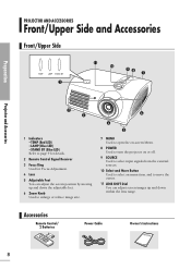
... the adjustable feet. 6 Zoom Knob Used to enlarge or reduce image size. 6 4 5 7 MENU Used to open the on-screen Menu. 8 POWER Used to turn the projector on or off. 9 SOURCE Used to select input signals from the external sources. 10 Select and Move Button Used to select an menu item, and... can adjust screen images up and down within the lens range. TEMP (Red LED) - Accessories Remote Control/ 2 Batteries Power Cable Owner's Instructions 8 LAMP (Blue LED) - PROJECTOR AND ACCESSORIES Front/Upper Side and Accessories Front/Upper Side 11 10 98 7 1 Preparation...
... the adjustable feet. 6 Zoom Knob Used to enlarge or reduce image size. 6 4 5 7 MENU Used to open the on-screen Menu. 8 POWER Used to turn the projector on or off. 9 SOURCE Used to select input signals from the external sources. 10 Select and Move Button Used to select an menu item, and... can adjust screen images up and down within the lens range. TEMP (Red LED) - Accessories Remote Control/ 2 Batteries Power Cable Owner's Instructions 8 LAMP (Blue LED) - PROJECTOR AND ACCESSORIES Front/Upper Side and Accessories Front/Upper Side 11 10 98 7 1 Preparation...
User Manual (ENGLISH)
Page 9
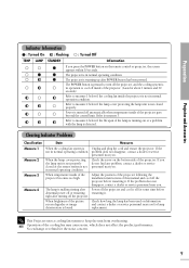
...it . If the problem does not disappear, contact a dealer or service personnel near you. The lamp is not in normal operating condition. This Projector uses a cooling fan system to measure 3. No exchange or refund for lamp replacement. Clearing Indicator Problems Classification Measure 1 Measure 2 Measure 3 ...Flashing : Turned Off TEMP LAMP STANDBY Information If you press the POWER button on the bottom side of the projector. Check the screw on the remote control or projector, the screen appears within 30 seconds. If you do not find any problem, contact a dealer or service ...
...it . If the problem does not disappear, contact a dealer or service personnel near you. The lamp is not in normal operating condition. This Projector uses a cooling fan system to measure 3. No exchange or refund for lamp replacement. Clearing Indicator Problems Classification Measure 1 Measure 2 Measure 3 ...Flashing : Turned Off TEMP LAMP STANDBY Information If you press the POWER button on the bottom side of the projector. Check the screw on the remote control or projector, the screen appears within 30 seconds. If you do not find any problem, contact a dealer or service ...
User Manual (ENGLISH)
Page 10
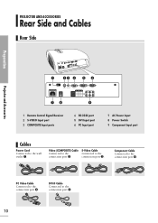
... connection port ´. PC Video Cable Connected to the connection port ˆ. 10 DVI-D Cable Connected to the connection port Ø. PROJECTOR AND ACCESSORIES Rear Side and Cables Rear Side Preparation Projector and Accessories 1 23 4 56 78 9 1 Remote Control Signal Receiver 2 S-VIDEO Input port 3 COMPOSITE Input ports 4 RS-232C port 5 DVI Input...
... connection port ´. PC Video Cable Connected to the connection port ˆ. 10 DVI-D Cable Connected to the connection port Ø. PROJECTOR AND ACCESSORIES Rear Side and Cables Rear Side Preparation Projector and Accessories 1 23 4 56 78 9 1 Remote Control Signal Receiver 2 S-VIDEO Input port 3 COMPOSITE Input ports 4 RS-232C port 5 DVI Input...
User Manual (ENGLISH)
Page 11
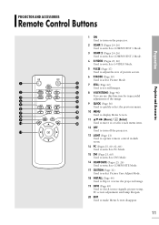
... Accessories 1 ON Used to turn on the projector. 2 COMP.1 (Pages 24~26) Used to switch to COMPONENT 1 Mode. 3 COMP.2 (Pages 24~26) Used to switch to COMPONENT 2 Mode. 4 S-VIDEO (Pages 23, 26) Used ... Menu Screen. 19 11 Move) / (Select) 10 20 Used to move to or select each menu item. 12 OFF 11 Used to turn off the projector. 13 LIGHT (Page 13) Used to operate remote control in dark room. 14 PC (Pages 25, 60, 62~66) Used to switch to PC Mode...
... Accessories 1 ON Used to turn on the projector. 2 COMP.1 (Pages 24~26) Used to switch to COMPONENT 1 Mode. 3 COMP.2 (Pages 24~26) Used to switch to COMPONENT 2 Mode. 4 S-VIDEO (Pages 23, 26) Used ... Menu Screen. 19 11 Move) / (Select) 10 20 Used to move to or select each menu item. 12 OFF 11 Used to turn off the projector. 13 LIGHT (Page 13) Used to operate remote control in dark room. 14 PC (Pages 25, 60, 62~66) Used to switch to PC Mode...
User Manual (ENGLISH)
Page 12
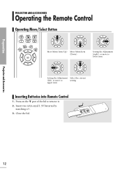
Preparation PROJECTOR AND ACCESSORIES Operating the Remote Control Operating Move/Select Button Move Menu Item (Up) Move Menu Item (Down) Setting the Adjustment (right), or move to setting upper item Inserting Batteries into Remote Control 1. Press on the part of the lid to lower item. Insert two AAA-sized 1.5V batteries by matching +/-. 3. Projector and Accessories 12 Close the lid. Setting the Adjustment Select the current (left), or move to remove it. 2.
Preparation PROJECTOR AND ACCESSORIES Operating the Remote Control Operating Move/Select Button Move Menu Item (Up) Move Menu Item (Down) Setting the Adjustment (right), or move to setting upper item Inserting Batteries into Remote Control 1. Press on the part of the lid to lower item. Insert two AAA-sized 1.5V batteries by matching +/-. 3. Projector and Accessories 12 Close the lid. Setting the Adjustment Select the current (left), or move to remove it. 2.
User Manual (ENGLISH)
Page 13
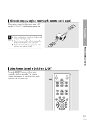
... not use new and used for long periods of time. LIGHT 13 The remote control buttons are lit for five seconds. Preparation Projector and Accessories Allowable range & angle of receiving the remote control signal The remote control is not used batteries together. Replace two batteries at the same ... Control in Dark Place (LIGHT) Press the LIGHT button of the remote controller for about 5 seconds and turn off automatically. CAUTION I Remove batteries when the projector is effective within a 30° angle 23~33 ft (7~10m) from children and dispose of them properly.
... not use new and used for long periods of time. LIGHT 13 The remote control buttons are lit for five seconds. Preparation Projector and Accessories Allowable range & angle of receiving the remote control signal The remote control is not used batteries together. Replace two batteries at the same ... Control in Dark Place (LIGHT) Press the LIGHT button of the remote controller for about 5 seconds and turn off automatically. CAUTION I Remove batteries when the projector is effective within a 30° angle 23~33 ft (7~10m) from children and dispose of them properly.
User Manual (ENGLISH)
Page 14
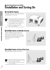
... to see the screen. The Translucent will show the horizontally flipped image. Preparation INSTALLATION AND BASIC ADJUSTMENTS Installation and Turning On To Install the Projector Install the projector so that the projection is not positioned perpendicular to the NOTE screen, the image may be installed on the ceiling NOTE in Front of...
... to see the screen. The Translucent will show the horizontally flipped image. Preparation INSTALLATION AND BASIC ADJUSTMENTS Installation and Turning On To Install the Projector Install the projector so that the projection is not positioned perpendicular to the NOTE screen, the image may be installed on the ceiling NOTE in Front of...
User Manual (ENGLISH)
Page 15
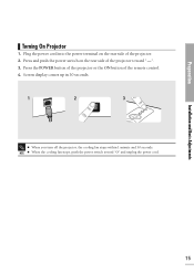
Press and push the power switch on the rear side of the projector. 2. Installation and Basic Adjustments 15 Preparation Turning On Projector 1. NOTE I When you turn off the projector, the cooling fan stops within 1 minute and 30 seconds. Plug the power cord into the power terminal on the rear side of the remote control. 4. Press the POWER button of the projector or the ON button of the projector toward "O" and unplug the power cord. Screen display comes up in 30 seconds. 1 2 3 I When the cooling fan stops, push the power switch toward "-". 3.
Press and push the power switch on the rear side of the projector. 2. Installation and Basic Adjustments 15 Preparation Turning On Projector 1. NOTE I When you turn off the projector, the cooling fan stops within 1 minute and 30 seconds. Plug the power cord into the power terminal on the rear side of the remote control. 4. Press the POWER button of the projector or the ON button of the projector toward "O" and unplug the power cord. Screen display comes up in 30 seconds. 1 2 3 I When the cooling fan stops, push the power switch toward "-". 3.
User Manual (ENGLISH)
Page 16
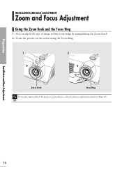
Preparation INSTALLATION AND BASIC ADJUSTMENTS Zoom and Focus Adjustment Using the Zoom Knob and the Focus Ring 1. Focus the picture on the screen using the Focus Ring. 1 2 Zoom Knob Focus Ring Focus may appear dim if the projector is installed at a shorter than recommended distance. (Page 20) NOTE Installation and Basic Adjustments 16 You can adjust the size of image within zoom range by manipulating the Zoom Knob. 2.
Preparation INSTALLATION AND BASIC ADJUSTMENTS Zoom and Focus Adjustment Using the Zoom Knob and the Focus Ring 1. Focus the picture on the screen using the Focus Ring. 1 2 Zoom Knob Focus Ring Focus may appear dim if the projector is installed at a shorter than recommended distance. (Page 20) NOTE Installation and Basic Adjustments 16 You can adjust the size of image within zoom range by manipulating the Zoom Knob. 2.
User Manual (ENGLISH)
Page 17
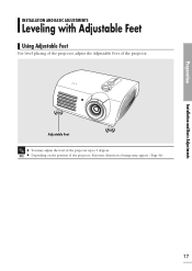
NOTE I You may adjust the level of image may appear. (Page 46) 17 Adjustable Feet I Depending on the position of the projector, Keystone distortion of the projector up to 5 degrees. Preparation Installation and Basic Adjustments INSTALLATION AND BASIC ADJUSTMENTS Leveling with Adjustable Feet Using Adjustable Feet For level placing of the projector, adjust the Adjustable Feet of the projector.
NOTE I You may adjust the level of image may appear. (Page 46) 17 Adjustable Feet I Depending on the position of the projector, Keystone distortion of the projector up to 5 degrees. Preparation Installation and Basic Adjustments INSTALLATION AND BASIC ADJUSTMENTS Leveling with Adjustable Feet Using Adjustable Feet For level placing of the projector, adjust the Adjustable Feet of the projector.
User Manual (ENGLISH)
Page 18
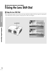
Lens Shift Dial UP DOWN Installation and Basic Adjustments 18 Preparation INSTALLATION AND BASIC ADJUSTMENTS Using the Lens Shift Dial Using the Lens Shift Dial Move the picture projected on the screen up and down within the lens range by turning the Lens Shift Dial on the top side of the projector with your fingers.
Lens Shift Dial UP DOWN Installation and Basic Adjustments 18 Preparation INSTALLATION AND BASIC ADJUSTMENTS Using the Lens Shift Dial Using the Lens Shift Dial Move the picture projected on the screen up and down within the lens range by turning the Lens Shift Dial on the top side of the projector with your fingers.
User Manual (ENGLISH)
Page 19
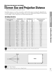
... a 80 to show images optimally on a flat, even surface and level the projector using the Zoom Knob or Focus Ring, or move the projector forward and backward. NOTE Screen Screen Y X I Z : Throw Distance NOTE I Z' : ....8/8.2 19.8/7.8 18.7/7.4 17.7/7.0 16.6/6.5 15.6/6.1 14.6/5.7 13.5/5.3 12.5/4.9 11.4/4.5 10.4/4.1 9.4/3.7 8.3/3.3 7.3/2.9 6.2/2.4 5.2/2.0 4.5/1.8 4.2/1.7 3.4/1.3 3.2/1.3 This projector is designed to 150 inch sized screen. Preparation Installation and Basic Adjustments INSTALLATION AND BASIC ADJUSTMENTS Screen Size and Projection Distance Check the following before...
... a 80 to show images optimally on a flat, even surface and level the projector using the Zoom Knob or Focus Ring, or move the projector forward and backward. NOTE Screen Screen Y X I Z : Throw Distance NOTE I Z' : ....8/8.2 19.8/7.8 18.7/7.4 17.7/7.0 16.6/6.5 15.6/6.1 14.6/5.7 13.5/5.3 12.5/4.9 11.4/4.5 10.4/4.1 9.4/3.7 8.3/3.3 7.3/2.9 6.2/2.4 5.2/2.0 4.5/1.8 4.2/1.7 3.4/1.3 3.2/1.3 This projector is designed to 150 inch sized screen. Preparation Installation and Basic Adjustments INSTALLATION AND BASIC ADJUSTMENTS Screen Size and Projection Distance Check the following before...
User Manual (ENGLISH)
Page 20
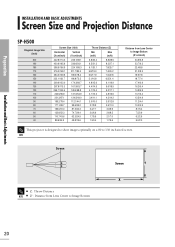
... Distance NOTE I Z' : Distance from Lens Center to Image Bottom (Z':cm/inch) 24.9/9.8 23.7/9.3 22.4/8.8 21.2/8.3 19.9/7.8 18.7/7.4 17.4/6.9 16.2/6.4 14.9/5.9 13.7/5.4 12.5/4.9 11.2/4.4 10.0/3.9 8.7/3.4 7.5/2.9 6.2/2.5 5.0/2.0 This projector is designed to show images optimally on a 80 to Image Bottom 20 Preparation Installation and Basic Adjustments INSTALLATION AND BASIC ADJUSTMENTS Screen Size and Projection...
... Distance NOTE I Z' : Distance from Lens Center to Image Bottom (Z':cm/inch) 24.9/9.8 23.7/9.3 22.4/8.8 21.2/8.3 19.9/7.8 18.7/7.4 17.4/6.9 16.2/6.4 14.9/5.9 13.7/5.4 12.5/4.9 11.2/4.4 10.0/3.9 8.7/3.4 7.5/2.9 6.2/2.5 5.0/2.0 This projector is designed to show images optimally on a 80 to Image Bottom 20 Preparation Installation and Basic Adjustments INSTALLATION AND BASIC ADJUSTMENTS Screen Size and Projection...
User Manual (ENGLISH)
Page 22
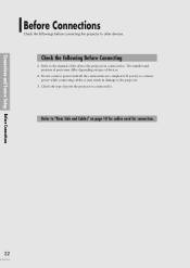
...all the connections are completed. Refer to the manual of the device the projector is connected to "Rear Side and Cables" on type of devices. 2. The number and position of ports the projector is connected to other devices. Connections and Source Setup Before Connections Before Connections... Check the followings before connecting the projector to . Check the following Before Connecting 1. Refer to . Check the type of ports may result in damage to the projector. 3. If you try to connect power while connecting cables, it may ...
...all the connections are completed. Refer to the manual of the device the projector is connected to "Rear Side and Cables" on type of devices. 2. The number and position of ports the projector is connected to other devices. Connections and Source Setup Before Connections Before Connections... Check the followings before connecting the projector to . Check the following Before Connecting 1. Refer to . Check the type of ports may result in damage to the projector. 3. If you try to connect power while connecting cables, it may ...
User Manual (ENGLISH)
Page 23
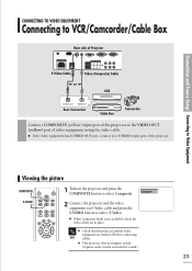
...via S-Video cable and press the S-VIDEO button to select Composite. I When Composite Mode is needed for sound.) 23 I Check that the projector and the video equipment are in place. I If the video equipment has S-VIDEO OUT port, connect it to S-VIDEO input port of ...video equipment using the video cable. Viewing the picture COMPOSITE 1 S-VIDEO 2 1 Turn on the projector and press the COMPOSITE button to select S-Video. I This projector does not support sound. (Separate audio system is not available, check the video cables are turned off before connecting NOTE...
...via S-Video cable and press the S-VIDEO button to select Composite. I When Composite Mode is needed for sound.) 23 I Check that the projector and the video equipment are in place. I If the video equipment has S-VIDEO OUT port, connect it to S-VIDEO input port of ...video equipment using the video cable. Viewing the picture COMPOSITE 1 S-VIDEO 2 1 Turn on the projector and press the COMPOSITE button to select S-Video. I This projector does not support sound. (Separate audio system is not available, check the video cables are turned off before connecting NOTE...
User Manual (ENGLISH)
Page 24
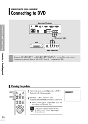
... When Component Mode is connected. Connections and Source Setup Connecting to Video Equipment CONNECTING TO VIDEO EQUIPMENT Connecting to DVD Rear side of Projector DVD Component Cable COMPONENT VIDEO OUT AUDIO OUT S-VIDEO OUT Rear Connection Connect COMPONENT1 or COMPONENT2 (Y/Pb/Pr) ports of the... projector to select Component1. Component1 2 Press the COMP.2 button to select Component2 if COMPONENT2 is not available, check that the component cables are ...
... When Component Mode is connected. Connections and Source Setup Connecting to Video Equipment CONNECTING TO VIDEO EQUIPMENT Connecting to DVD Rear side of Projector DVD Component Cable COMPONENT VIDEO OUT AUDIO OUT S-VIDEO OUT Rear Connection Connect COMPONENT1 or COMPONENT2 (Y/Pb/Pr) ports of the... projector to select Component1. Component1 2 Press the COMP.2 button to select Component2 if COMPONENT2 is not available, check that the component cables are ...
User Manual (ENGLISH)
Page 25
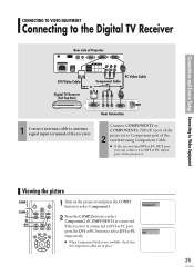
...is not available, check that the component cables are in place. 25 Rear Connection Connect COMPONENT1 or COMPONENT2 (Y/Pb/Pr) port of the 2 projector to select Component1. I If the receiver has DVI or PC OUT port, you can connect it to select DVI or PC DVI respectively. ...using Component Cable. Connections and Source Setup Connecting to Video Equipment CONNECTING TO VIDEO EQUIPMENT Connecting to the Digital TV Receiver Rear side of Projector DVI Video Cable Digital TV Receiver (Set-Top Box) Component Cable or PC Video Cable 1 Connect antenna cable to select Component2 if ...
...is not available, check that the component cables are in place. 25 Rear Connection Connect COMPONENT1 or COMPONENT2 (Y/Pb/Pr) port of the 2 projector to select Component1. I If the receiver has DVI or PC OUT port, you can connect it to select DVI or PC DVI respectively. ...using Component Cable. Connections and Source Setup Connecting to Video Equipment CONNECTING TO VIDEO EQUIPMENT Connecting to the Digital TV Receiver Rear side of Projector DVI Video Cable Digital TV Receiver (Set-Top Box) Component Cable or PC Video Cable 1 Connect antenna cable to select Component2 if ...


