
Owners Instructions
Page 1
... separate this item for disposal. BP68-00430C-00 Owner's Instructions SP-H800 O W N E R ' S I N S T R U C T I O N S Europe Only Correct Disposal of This Product (Waste Electrical & Electronic Equipment) (Applicable in the European Union and other European countries with separate collection systems) This marking shown on the product or its working life. Household users should contact their local government office, for details of...
... separate this item for disposal. BP68-00430C-00 Owner's Instructions SP-H800 O W N E R ' S I N S T R U C T I O N S Europe Only Correct Disposal of This Product (Waste Electrical & Electronic Equipment) (Applicable in the European Union and other European countries with separate collection systems) This marking shown on the product or its working life. Household users should contact their local government office, for details of...
Owners Instructions
Page 2
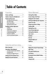
...and Design...4 Caution on Lamp Use and Replacement ...5 Projector and Accessories Front/Upper Side and Accessories ...8 Rear Side and Cables ...10 Remote Control Buttons ...11 Operating the Remote Control...12 Installation and Basic Adjustments Installation ...14 Turning ON/OFF ...15 Zooming and Focus Adjustment...16 Leveling with Adjustable Feet ...17 Using the Lens Shift Dial...18 Screen Size and Projection Distance...19 Picture Adjustment Selecting Picture Mode ...30 Custom Settings of the Picture ...31 Changing the Color Standard ...32 Selecting and Adjusting Color Temperature ...33 Gamma...
...and Design...4 Caution on Lamp Use and Replacement ...5 Projector and Accessories Front/Upper Side and Accessories ...8 Rear Side and Cables ...10 Remote Control Buttons ...11 Operating the Remote Control...12 Installation and Basic Adjustments Installation ...14 Turning ON/OFF ...15 Zooming and Focus Adjustment...16 Leveling with Adjustable Feet ...17 Using the Lens Shift Dial...18 Screen Size and Projection Distance...19 Picture Adjustment Selecting Picture Mode ...30 Custom Settings of the Picture ...31 Changing the Color Standard ...32 Selecting and Adjusting Color Temperature ...33 Gamma...
Owners Instructions
Page 3
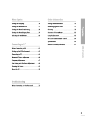
... Optional Parts...77 Glossary ...78 Structure of Screen Menu ...80 Lamp Replacement ...83 RS-232C Connection and Control ...84 Specifications ...86 Preparation Connecting to PC Before Connecting to PC ...62 Setting up the PC Environment ...63 Connecting to PC...64 Automatic Picture Adjustment ...66 Frequency Adjustment ...67 Fine Tuning with the Phase Adjustment ...68 Zooming the Screen ...69 Reset the PC ...70 Remote Control Specifications ...87 Table of Contents Troubleshooting Before Contacting Service Personnel...
... Optional Parts...77 Glossary ...78 Structure of Screen Menu ...80 Lamp Replacement ...83 RS-232C Connection and Control ...84 Specifications ...86 Preparation Connecting to PC Before Connecting to PC ...62 Setting up the PC Environment ...63 Connecting to PC...64 Automatic Picture Adjustment ...66 Frequency Adjustment ...67 Fine Tuning with the Phase Adjustment ...68 Zooming the Screen ...69 Reset the PC ...70 Remote Control Specifications ...87 Table of Contents Troubleshooting Before Contacting Service Personnel...

Owners Instructions
Page 5
Caution on Lamp Use and Replacement Projector Lamp
Caution on Lamp Use and Replacement Projector Lamp

Owners Instructions
Page 8
... Remote Control/ 2 Batteries Power Cable Owner's Instructions 8 Zoom Knob Used to page 9 for Focus Adjustment. 7 6 MENU Use this button to move to move forward in a menu. TEMP (Red LED) - STAND BY (Blue LED) Refer to enlarge or reduce image size. 6 11 10 9 8 7 1 2 3 4 5 Indicators - SOURCE Used to select input signals from the external sources. 8 9 10 Select and Move Button Use this button to enter or exit a menu or to or select an item within the lens range. Remote Control Signal Receiver Focus Ring Used for details. POWER Used to turn the projector...
... Remote Control/ 2 Batteries Power Cable Owner's Instructions 8 Zoom Knob Used to page 9 for Focus Adjustment. 7 6 MENU Use this button to move to move forward in a menu. TEMP (Red LED) - STAND BY (Blue LED) Refer to enlarge or reduce image size. 6 11 10 9 8 7 1 2 3 4 5 Indicators - SOURCE Used to select input signals from the external sources. 8 9 10 Select and Move Button Use this button to enter or exit a menu or to or select an item within the lens range. Remote Control Signal Receiver Focus Ring Used for details. POWER Used to turn the projector...
Owners Instructions
Page 9
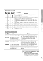
... the POWER button on the remote control or projector, the screen appears within 30 seconds. Indicator Information : Turned on TEMP LAMP : Blinks STANDBY : Turned off Information If you . This state appears when the projector is preparing an operation after time and then turn off the projector, and the cooling system is found. If the problem does not disappear, contact a dealer or service personnel near you . Check how long the lamp has been used...
... the POWER button on the remote control or projector, the screen appears within 30 seconds. Indicator Information : Turned on TEMP LAMP : Blinks STANDBY : Turned off Information If you . This state appears when the projector is preparing an operation after time and then turn off the projector, and the cooling system is found. If the problem does not disappear, contact a dealer or service personnel near you . Check how long the lamp has been used...

Owners Instructions
Page 11
... 31) Used to select Picture User Adjust Mode. 18 INSTALL (Page 48) Used to flip or reverse the projected image. 19 INFO (Page 53) Used to check source signals, picture setup, PC screen adjustment and lamp lifespan. 20 EXIT Used to quickly select the previous menu. Preparation COMP.2 (Pages 24~27) Used to switch to see still images. P.SIZE (Page 37) Used to adjust the size of the image. STILL (Page 45) Used to COMPONENT 2 Mode. Projector and Accessories 10 MENU Used to display Menu Screen. 11...
... 31) Used to select Picture User Adjust Mode. 18 INSTALL (Page 48) Used to flip or reverse the projected image. 19 INFO (Page 53) Used to check source signals, picture setup, PC screen adjustment and lamp lifespan. 20 EXIT Used to quickly select the previous menu. Preparation COMP.2 (Pages 24~27) Used to switch to see still images. P.SIZE (Page 37) Used to adjust the size of the image. STILL (Page 45) Used to COMPONENT 2 Mode. Projector and Accessories 10 MENU Used to display Menu Screen. 11...

Owners Instructions
Page 15
A picture will be displayed on the rear side of the projector toward "-". 3. Press the POWER button of the projector or the ON button of the projector. 2. Preparation 1 2 3 Installation and Basic Adjustments Press and push the power switch on the screen in approximately 30 seconds. Plug the power cord into the power terminal on the rear side of the remote control. 4. INSTALLATION AND BASIC ADJUSTMENTS Turning ON/OFF Turning On Projector 1.
A picture will be displayed on the rear side of the projector toward "-". 3. Press the POWER button of the projector or the ON button of the projector. 2. Preparation 1 2 3 Installation and Basic Adjustments Press and push the power switch on the screen in approximately 30 seconds. Plug the power cord into the power terminal on the rear side of the remote control. 4. INSTALLATION AND BASIC ADJUSTMENTS Turning ON/OFF Turning On Projector 1.

Owners Instructions
Page 16
You can adjust the size of image within zoom range by manipulating the Zoom Knob. 2. Focus the picture on the screen using the Focus Ring. INSTALLATION AND BASIC ADJUSTMENTS Zoom and Focus Adjustment Using the Zoom Knob and the Focus Ring 1. Preparation Installation and Basic Adjustments 1 2 Zoom Knob Focus Ring Focus may appear dim if the projector is installed at a shorter than recommended distance. (Page 19) NOTE 16
You can adjust the size of image within zoom range by manipulating the Zoom Knob. 2. Focus the picture on the screen using the Focus Ring. INSTALLATION AND BASIC ADJUSTMENTS Zoom and Focus Adjustment Using the Zoom Knob and the Focus Ring 1. Preparation Installation and Basic Adjustments 1 2 Zoom Knob Focus Ring Focus may appear dim if the projector is installed at a shorter than recommended distance. (Page 19) NOTE 16

Owners Instructions
Page 19
....4 9.1 8.6 8.2 7.7 7.3 6.8 6.4 5.9 5.5 5.0 4.5 4.1 3.6 3.2 2.7 2.3 1.9 1.8 1.5 1.4 Distance from Lens Center to Image Bottom (Z':cm/inch) 31.2 26.0 20.8 19.8 18.7 17.7 16.6 15.6 14.6 13.5 12.5 11.4 10.4 9.4 8.3 7.3 6.2 5.2 4.5 4.2 3.4 3.2 Installation and Basic Adjustments NOTE This projector is designed to show images optimally on a flat, even surface and level the projector using the Zoom Knob or Focus Ring, or move the projector forward and backward. INSTALLATION AND BASIC ADJUSTMENTS Screen Size and Projection Distance Install the projector on...
....4 9.1 8.6 8.2 7.7 7.3 6.8 6.4 5.9 5.5 5.0 4.5 4.1 3.6 3.2 2.7 2.3 1.9 1.8 1.5 1.4 Distance from Lens Center to Image Bottom (Z':cm/inch) 31.2 26.0 20.8 19.8 18.7 17.7 16.6 15.6 14.6 13.5 12.5 11.4 10.4 9.4 8.3 7.3 6.2 5.2 4.5 4.2 3.4 3.2 Installation and Basic Adjustments NOTE This projector is designed to show images optimally on a flat, even surface and level the projector using the Zoom Knob or Focus Ring, or move the projector forward and backward. INSTALLATION AND BASIC ADJUSTMENTS Screen Size and Projection Distance Install the projector on...
Owners Instructions
Page 25
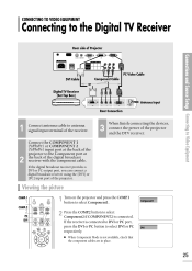
... button to antenna signal input terminal of the receiver. If the digital broadcast receiver provides a DVI or PC output port, you can connect a digital broadcast receiver using the [DVI] or [PC] input port of the projector. 3 When finish connecting the devices, connect the power of the digital broadcast receiver with the component cable. CONNECTING TO VIDEO EQUIPMENT Connecting to the Digital TV Receiver Rear side of Projector Connections and Source Setup Connecting to Video Equipment PC Video Cable...
... button to antenna signal input terminal of the receiver. If the digital broadcast receiver provides a DVI or PC output port, you can connect a digital broadcast receiver using the [DVI] or [PC] input port of the projector. 3 When finish connecting the devices, connect the power of the digital broadcast receiver with the component cable. CONNECTING TO VIDEO EQUIPMENT Connecting to the Digital TV Receiver Rear side of Projector Connections and Source Setup Connecting to Video Equipment PC Video Cable...

Owners Instructions
Page 33
... bright places and saved in D Picture Mode. Color Temperature Menu 5500K Used to deliver optimal image quality for the most precise tint. 8000K The color temperature appropriate to Picture, then press the button. Picture Picture Mode Custom Picture Picture Size Position DNIe Noise Reduction The main menu is manufactured, and may deliver the most video productions. Selecting and Adjusting Color Temperature You can change tint of Movie2 is set as a shop. MENU 1 2, 3, 4, 5, 6, 7 Picture Adjustment 2, 3, 4, 6, 7 EXIT 8 1 2 3 4 5 6 7 8 Press the MENU button.
... bright places and saved in D Picture Mode. Color Temperature Menu 5500K Used to deliver optimal image quality for the most precise tint. 8000K The color temperature appropriate to Picture, then press the button. Picture Picture Mode Custom Picture Picture Size Position DNIe Noise Reduction The main menu is manufactured, and may deliver the most video productions. Selecting and Adjusting Color Temperature You can change tint of Movie2 is set as a shop. MENU 1 2, 3, 4, 5, 6, 7 Picture Adjustment 2, 3, 4, 6, 7 EXIT 8 1 2 3 4 5 6 7 8 Press the MENU button.

Owners Instructions
Page 34
MENU 1 Picture Adjustment Gamma Correction 2, 3, 4, 5 .../ Gamma Correction An image compensation function that controls the settings according to the video properties.
MENU 1 Picture Adjustment Gamma Correction 2, 3, 4, 5 .../ Gamma Correction An image compensation function that controls the settings according to the video properties.
Owners Instructions
Page 62
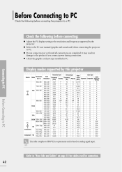
... port type installed in damage to the product if you connect power during connection. Do not connect power cord until all connections are completed. NOTE Refer to PC. It may result in PC. Before Connecting to PC Check the following before connecting the projector to a PC. Refer to the PC user manual (graphic and sound card) when connecting the projector to "Rear Side and Cables" on analog signal input. Display modes supported by the projector...
... port type installed in damage to the product if you connect power during connection. Do not connect power cord until all connections are completed. NOTE Refer to PC. It may result in PC. Before Connecting to PC Check the following before connecting the projector to a PC. Refer to the PC user manual (graphic and sound card) when connecting the projector to "Rear Side and Cables" on analog signal input. Display modes supported by the projector...

Owners Instructions
Page 64
.... This product supports Plug & Play. Viewing the PC Screen PC Turn on the rear side of the projector to the monitor output port of Projector Rear Connection DVI-D Cable or PC Video Cable Connecting to PC Connecting to PC 64 DVI-D Port 1 Connect PC port on the projector and press the PC button 1 to the projector and use it to select DVI. Using PC Video Cable or DVI Cable Rear side of PC using PC video cable.
.... This product supports Plug & Play. Viewing the PC Screen PC Turn on the rear side of the projector to the monitor output port of Projector Rear Connection DVI-D Cable or PC Video Cable Connecting to PC Connecting to PC 64 DVI-D Port 1 Connect PC port on the projector and press the PC button 1 to the projector and use it to select DVI. Using PC Video Cable or DVI Cable Rear side of PC using PC video cable.

Owners Instructions
Page 72
... projector and adjust the Zoom Control and the Focus Ring. Image is an optional accessory. Ceiling bracket is distorted or trapezoidal. Note Page 15 Pages 16~19 Want to page 50. Installation and Connection Symptoms No Power. Relocate the position so that the power cord in place and the power switch on "-". Pages 23~25 Menu and Remote Control Symptoms Remote control does not work. Be sure that the connection cable (video) is turned...
... projector and adjust the Zoom Control and the Focus Ring. Image is an optional accessory. Ceiling bracket is distorted or trapezoidal. Note Page 15 Pages 16~19 Want to page 50. Installation and Connection Symptoms No Power. Relocate the position so that the power cord in place and the power switch on "-". Pages 23~25 Menu and Remote Control Symptoms Remote control does not work. Be sure that the connection cable (video) is turned...
Owners Instructions
Page 78
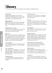
... poor video signals, some unnecessary video signals may not display properly or the dark screen looks milky-white. Color Temperature Color temperature is dark. To view satellite broadcasts, you have to subscribe to connect and use various input and output devices. 78 Other Information Glossary Black Level sets the light level of the darkest portion of the video signal to the United States terrestrial digital broadcast specifications, or ATSC. Backlight Remote Control The buttons...
... poor video signals, some unnecessary video signals may not display properly or the dark screen looks milky-white. Color Temperature Color temperature is dark. To view satellite broadcasts, you have to subscribe to connect and use various input and output devices. 78 Other Information Glossary Black Level sets the light level of the darkest portion of the video signal to the United States terrestrial digital broadcast specifications, or ATSC. Backlight Remote Control The buttons...

Owners Instructions
Page 79
... digital signals for digital devices. S-VIDEO IN Port This is an optical part that decomposes white rays into basic colors organizing the screen. 79 Glossary Other Information DLP (Digital Light Processing) DLP is a digital display technology using a DMD panel developed by TI (Texas Instruments) of DLP technology. DLP HD2+, DC3 This is an implementation of the United States. 5x Speed, 8 Segment Color Wheel This is called super video. DMD (Digital Micromirror Device) A DMD panel is a grade of video signal...
... digital signals for digital devices. S-VIDEO IN Port This is an optical part that decomposes white rays into basic colors organizing the screen. 79 Glossary Other Information DLP (Digital Light Processing) DLP is a digital display technology using a DMD panel developed by TI (Texas Instruments) of DLP technology. DLP HD2+, DC3 This is an implementation of the United States. 5x Speed, 8 Segment Color Wheel This is called super video. DMD (Digital Micromirror Device) A DMD panel is a grade of video signal...

Owners Instructions
Page 85
... 90 120 EXIT Menu Option Language Factory Default Information LED V-Keystone PC Test Pattern 1 or 0 1 or 0 1 or 0 1 or 0 1 or 0 1 or 0 Light Setting Setup Install Film Mode Overscan Color Control RETURN Picture Black Level CONTROL ITEMS 7.5 IRE 0 IRE OFF Monochrome Red Green Blue On Off On Off Front-Floor Front-Ceiling Rear-Floor Rear-Ceiling Theater Bright Crosshatch Screen Size Color Standard Red Green Blue White 6500K_White V-Keystone (-50~50) Auto Adjustment Coarse (0~2000) Fine (0~255) Zoom (0~3) PC Reset CONFIRM OK On...
... 90 120 EXIT Menu Option Language Factory Default Information LED V-Keystone PC Test Pattern 1 or 0 1 or 0 1 or 0 1 or 0 1 or 0 1 or 0 Light Setting Setup Install Film Mode Overscan Color Control RETURN Picture Black Level CONTROL ITEMS 7.5 IRE 0 IRE OFF Monochrome Red Green Blue On Off On Off Front-Floor Front-Ceiling Rear-Floor Rear-Ceiling Theater Bright Crosshatch Screen Size Color Standard Red Green Blue White 6500K_White V-Keystone (-50~50) Auto Adjustment Coarse (0~2000) Fine (0~255) Zoom (0~3) PC Reset CONFIRM OK On...

Owners Instructions
Page 86
.... Model Size Resolution Lamp Power Type Life Time Power Consumption Voltage Frequency Dimensions Weight Accessories Key Features Brightness Contrast (Theatre Mode) Screen Size Classification Panel SP-H800 0.8"(HD2+, DC3) 1280 x 720 250W UHP 2000Hrs 350W AC 100-240V~ 50/60Hz 384 x 425 x 177 mm 9.0 kg / 19.8 lb Owner's Instructions, Power Cord, Remote control, Batteries 700 ANSI 3800 : 1 Diagonal 30.385~300" 1.0 ~ 13.6 m Vertical 1) Connector Type: DVI-D 2) Available Format: PC - VGA~SXGA...
.... Model Size Resolution Lamp Power Type Life Time Power Consumption Voltage Frequency Dimensions Weight Accessories Key Features Brightness Contrast (Theatre Mode) Screen Size Classification Panel SP-H800 0.8"(HD2+, DC3) 1280 x 720 250W UHP 2000Hrs 350W AC 100-240V~ 50/60Hz 384 x 425 x 177 mm 9.0 kg / 19.8 lb Owner's Instructions, Power Cord, Remote control, Batteries 700 ANSI 3800 : 1 Diagonal 30.385~300" 1.0 ~ 13.6 m Vertical 1) Connector Type: DVI-D 2) Available Format: PC - VGA~SXGA...


