User Manual
Page 1
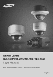
Network Camera SNB-5000/SND-5080/SND-5080F/SNV-5080 User Manual Before installing and operating this product, please read this manual thoroughly. English
Network Camera SNB-5000/SND-5080/SND-5080F/SNV-5080 User Manual Before installing and operating this product, please read this manual thoroughly. English
User Manual
Page 7
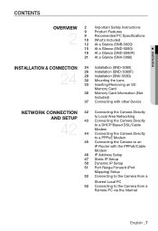
... 9 Recomended PC Specifications 10 What's Included 12 At a Glance (SNB-5000) 15 At a Glance (SND-5080) 18 At a Glance (SND-5080F) 21 At a Glance (SNV-5080) INSTALLATION & CONNECTION 24 24 Installation (SND-5080) 26 Installation (SND-5080F) 28 Installation (SNV-5080) 32 Mounting the Lens 33 Inserting/Removing an SD Memory Card 36 Memory Card Information (Not Included...
... 9 Recomended PC Specifications 10 What's Included 12 At a Glance (SNB-5000) 15 At a Glance (SND-5080) 18 At a Glance (SND-5080F) 21 At a Glance (SNV-5080) INSTALLATION & CONNECTION 24 24 Installation (SND-5080) 26 Installation (SND-5080F) 28 Installation (SNV-5080) 32 Mounting the Lens 33 Inserting/Removing an SD Memory Card 36 Memory Card Information (Not Included...
User Manual
Page 10
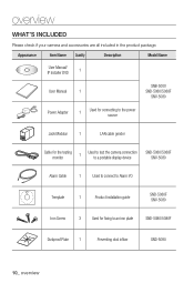
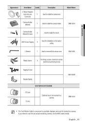
... product package. Appearance Item Name Quantity Description Model Name User Manual/ IP Installer DVD 1 User Manual 1 SNB-5000 SND-5080/5080F SNV-5080 Power Adapter 1 Used for connecting to the power source Jack Modular 1 LAN cable gender Cable for the testing monitor ...1 Used to test the camera connection to a portable display device SND-5080/5080F SNV-5080 Alarm Cable 1 Used to connect to Alarm I/O Template 1 Product installation guide SND-5080F SNV-5080 Iron Screw 3 Used for fixing to an iron plate SND-5080/5080F Dustproof Plate 1 Preventing dust inflow...
... product package. Appearance Item Name Quantity Description Model Name User Manual/ IP Installer DVD 1 User Manual 1 SNB-5000 SND-5080/5080F SNV-5080 Power Adapter 1 Used for connecting to the power source Jack Modular 1 LAN cable gender Cable for the testing monitor ...1 Used to test the camera connection to a portable display device SND-5080/5080F SNV-5080 Alarm Cable 1 Used to connect to Alarm I/O Template 1 Product installation guide SND-5080F SNV-5080 Iron Screw 3 Used for fixing to an iron plate SND-5080/5080F Dustproof Plate 1 Preventing dust inflow...
User Manual
Page 11
...) Screws 2 Used to install the mount ASSY-Screw Tapping 4 Used for installation on the wall or ceiling L Wrench 1 Used to remove/fix the dome cover SNV-5080 Plastic Anchor 4 For fixing a screw, Inserted in a hole (reinforced anchoring force) Tapping Screw Bracket Safety Lens Options (not included) CS Lens C Lens Optional lens to...
...) Screws 2 Used to install the mount ASSY-Screw Tapping 4 Used for installation on the wall or ceiling L Wrench 1 Used to remove/fix the dome cover SNV-5080 Plastic Anchor 4 For fixing a screw, Inserted in a hole (reinforced anchoring force) Tapping Screw Bracket Safety Lens Options (not included) CS Lens C Lens Optional lens to...
User Manual
Page 21
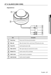
Used to connect a PoE or LAN cable. Used to plug the power cable. AT A GLANCE (SNV-5080) Appearance M OVERVIEW Item Dome Cover Main unit Power Port Video Out Port Network Port Audio In Jack Audio Out Jack Description Dome cover for the lens and unit protection. Main unit includes the lens, switch board, PCB boards and screws. English _21 Used to connect to the monitor. Video signal output port connected to speakers. Used to connect to a microphone.
Used to connect a PoE or LAN cable. Used to plug the power cable. AT A GLANCE (SNV-5080) Appearance M OVERVIEW Item Dome Cover Main unit Power Port Video Out Port Network Port Audio In Jack Audio Out Jack Description Dome cover for the lens and unit protection. Main unit includes the lens, switch board, PCB boards and screws. English _21 Used to connect to the monitor. Video signal output port connected to speakers. Used to connect to a microphone.
User Manual
Page 28
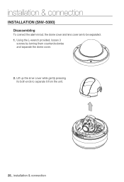
Using the L-wrench provided, loosen 3 screws by turning them counterclockwise and separate the dome cover. 2. installation & connection INSTALLATION (SNV-5080) Disassembling To connect the alarm in/out, the dome cover and lens cover are to separate it from the unit. 28_ installation & connection Lift up the inner cover while gently pressing its both ends to be separated. 1.
Using the L-wrench provided, loosen 3 screws by turning them counterclockwise and separate the dome cover. 2. installation & connection INSTALLATION (SNV-5080) Disassembling To connect the alarm in/out, the dome cover and lens cover are to separate it from the unit. 28_ installation & connection Lift up the inner cover while gently pressing its both ends to be separated. 1.
User Manual
Page 31
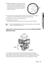
... right is referred to as "Panning", while tilting the angle is stopped by matching to the installation instructions of SND-5080F. (pages 26~27) Adjusting the monitoring direction for the camera (SND-5080/SND5080F/SNV-5080) Panning Tilting Lens rotation You can adjust the camera direction only when the camera is 220° for the...
... right is referred to as "Panning", while tilting the angle is stopped by matching to the installation instructions of SND-5080F. (pages 26~27) Adjusting the monitoring direction for the camera (SND-5080/SND5080F/SNV-5080) Panning Tilting Lens rotation You can adjust the camera direction only when the camera is 220° for the...
User Manual
Page 38
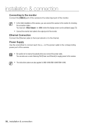
... cable to the output port of the camera, you connect the power cable. Ethernet Connection Connect the Ethernet cable to the local network or to SND-5080/SND-5080F/SNV-5080. 38_ installation & connection You can be activated. (page 72) Connect the monitor test cable to the corresponding power port of the monitor...
... cable to the output port of the camera, you connect the power cable. Ethernet Connection Connect the Ethernet cable to the local network or to SND-5080/SND-5080F/SNV-5080. 38_ installation & connection You can be activated. (page 72) Connect the monitor test cable to the corresponding power port of the monitor...
User Manual
Page 41
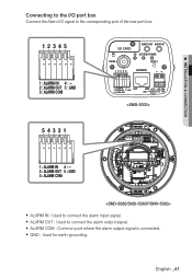
y ALARM OUT : Used to connect the alarm input signal. M INSTALLATION & CONNECTION Connecting to the I/O port box Connect the Alarm I/O signal to the corresponding port of the rear port box. 1 2 3 4 5 1 : ALARM IN 4 : 2 : ALARM OUT 5 : GND 3 : ALARM COM SD CARD AUDIO OUT AUDIO IN SD SYSTEM POWER VIDEO RESET 1 2 3 4 5 NETWORK 1 : ALARM IN 4 : 2 : ALARM OUT 5 : GND ACT 3 : ALARM COM LINK GND AC 24V DC 12V 5 4 3 2 1 1 : ALARM IN 4 : 2 : ALARM OUT 5 : GND 3 : ALARM COM y ALARM IN : Used to connect the alarm output signal. y GND : Used for earth-grounding. English _41 y ...
y ALARM OUT : Used to connect the alarm input signal. M INSTALLATION & CONNECTION Connecting to the I/O port box Connect the Alarm I/O signal to the corresponding port of the rear port box. 1 2 3 4 5 1 : ALARM IN 4 : 2 : ALARM OUT 5 : GND 3 : ALARM COM SD CARD AUDIO OUT AUDIO IN SD SYSTEM POWER VIDEO RESET 1 2 3 4 5 NETWORK 1 : ALARM IN 4 : 2 : ALARM OUT 5 : GND ACT 3 : ALARM COM LINK GND AC 24V DC 12V 5 4 3 2 1 1 : ALARM IN 4 : 2 : ALARM OUT 5 : GND 3 : ALARM COM y ALARM IN : Used to connect the alarm output signal. y GND : Used for earth-grounding. English _41 y ...

User Manual
Page 88
...(Ø)mm Net 438g 525g / 765g 1,340g Body Dark Grey White Case Metal Plastic Aluminum (IP66) 88_ appendix Viewing Angle Wide - appendix Items SNB-5000 SND-5080/F SNV-5080 Focal Length - 2.8~10mm Zoom ratio - Lens Tele -
...(Ø)mm Net 438g 525g / 765g 1,340g Body Dark Grey White Case Metal Plastic Aluminum (IP66) 88_ appendix Viewing Angle Wide - appendix Items SNB-5000 SND-5080/F SNV-5080 Focal Length - 2.8~10mm Zoom ratio - Lens Tele -