

User Manual
Page 9
.... POWER REC DIGITAL VIDEO RECORDER DVR Adapter / Power Cable Mouse Remote Control / Battery (AAA x 2) SEB-1005R (4EA) Model : SDE-3003 SEB-1007R (4EA) Model : SDE-3001 SEB-1005R (Bracket 4EA, Screws 12EA) SEB-1007R (Bracket 4EA, Screws 12EA) Camera Cables(4EA), 18.3m (60ft) / Model : SDE-3003 Model : SDE-3001 Network Cables Network Viewer Software User Manual CD, Quick Connect...
.... POWER REC DIGITAL VIDEO RECORDER DVR Adapter / Power Cable Mouse Remote Control / Battery (AAA x 2) SEB-1005R (4EA) Model : SDE-3003 SEB-1007R (4EA) Model : SDE-3001 SEB-1005R (Bracket 4EA, Screws 12EA) SEB-1007R (Bracket 4EA, Screws 12EA) Camera Cables(4EA), 18.3m (60ft) / Model : SDE-3003 Model : SDE-3001 Network Cables Network Viewer Software User Manual CD, Quick Connect...
User Manual
Page 11
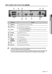
USB connector port. 1~4, G : Alarm Input port. 1, COM : Alarm Output port. Camera and DVR power input port. M If using the VGA cable, the source from BNC will be displayed. English _11 Video Signal Output Port (RCA jack). Audio Signal Output Port (RCA jack). Then, the BNC port ... OSD menus. Audio input signal port (RCA jack, CH1). For SEB-1006R (MIC integrated camera), it is also recommended not to connect other input devices to the AUDIO IN port. If you connect the VGA cable after the system boot, only the video signal from VGA will be displayed as main...
USB connector port. 1~4, G : Alarm Input port. 1, COM : Alarm Output port. Camera and DVR power input port. M If using the VGA cable, the source from BNC will be displayed. English _11 Video Signal Output Port (RCA jack). Audio Signal Output Port (RCA jack). Then, the BNC port ... OSD menus. Audio input signal port (RCA jack, CH1). For SEB-1006R (MIC integrated camera), it is also recommended not to connect other input devices to the AUDIO IN port. If you connect the VGA cable after the system boot, only the video signal from VGA will be displayed as main...
User Manual
Page 15
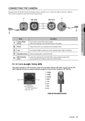
...Sensor Detects incoming light to the DVR without using a particular power cable. You can use . GND 5. 12V 6. CONNECTING WITH OTHER DEVICE CONNECTING THE CAMERA Equipped with the LAN cable. You can use the UTP direct cable (all of 8 pins are used to cover relatively longer range... not compliant with the IR LED and the illumination sensor, enables you to fit the camera bracket. b IR LED These infrared LED's are two grooves; e DVR Connection Cable Connect the cable directly to control the IR LED. CVBS+ 2. AUDIO 4. N.C 7. one on the top and...
...Sensor Detects incoming light to the DVR without using a particular power cable. You can use . GND 5. 12V 6. CONNECTING WITH OTHER DEVICE CONNECTING THE CAMERA Equipped with the LAN cable. You can use the UTP direct cable (all of 8 pins are used to cover relatively longer range... not compliant with the IR LED and the illumination sensor, enables you to fit the camera bracket. b IR LED These infrared LED's are two grooves; e DVR Connection Cable Connect the cable directly to control the IR LED. CVBS+ 2. AUDIO 4. N.C 7. one on the top and...

User Manual
Page 16
... the selected position can sustain the weight of the bracket, and screws turn the camera clockwise. wall or ceiling J You should be careful when installing the BOX camera outdoors because the cable connectors may be installed on the wall, ceiling or shelf. connecting with impurities.... Use the screw bolts (M4 X L15) to install the camera on the wall, ceiling, shelf or a desired position using ...
... the selected position can sustain the weight of the bracket, and screws turn the camera clockwise. wall or ceiling J You should be careful when installing the BOX camera outdoors because the cable connectors may be installed on the wall, ceiling or shelf. connecting with impurities.... Use the screw bolts (M4 X L15) to install the camera on the wall, ceiling, shelf or a desired position using ...

User Manual
Page 17
... screw of the equipments to lock the camera in position. 5. Attach the camera bracket to the camera. Loosen the handle by rotating the camera clockwise. 4. Choose an installation site that can sufficiently support the weight of the camera bracket by turning it clockwise to be installed. 2. Connect the camera cable to the wall using the supplied screws...
... screw of the equipments to lock the camera in position. 5. Attach the camera bracket to the camera. Loosen the handle by rotating the camera clockwise. 4. Choose an installation site that can sufficiently support the weight of the camera bracket by turning it clockwise to be installed. 2. Connect the camera cable to the wall using the supplied screws...

