
User Manual
Page 2
...own responsibility. The warranty period is the registered logo of this document. However, the followings are the registered trademark of Samsung Techwin. All rights reserved. Restriction Samsung Techwin Co., Ltd shall reserve the copyright of this document without formal authorization of their respective company. y Deteriorated performance... this document and the subsequent results shall be reproduced, distributed or changed, partially or wholly, without prior notice. Samsung Techwin will resolve the problem for free of time 12X SPEED DOME CAMERA User Manual Copyright ©2010...
...own responsibility. The warranty period is the registered logo of this document. However, the followings are the registered trademark of Samsung Techwin. All rights reserved. Restriction Samsung Techwin Co., Ltd shall reserve the copyright of this document without formal authorization of their respective company. y Deteriorated performance... this document and the subsequent results shall be reproduced, distributed or changed, partially or wholly, without prior notice. Samsung Techwin will resolve the problem for free of time 12X SPEED DOME CAMERA User Manual Copyright ©2010...

User Manual
Page 3
...;re. 4. SAFETY INFORMATION safety information CAUTION RISK OF ELECTRIC SHOCK. This symbol indicates that dangerous voltage consisting a risk of camera may cause explosion, fire, electric shock, or damage to a single adapter. English English _ 3 REFER SERVICING TO QUALIFIED... SERVICE PERSONNEL. Do not connect multiple cameras to the product. 3. When installing the camera, fasten it securely and firmly. Do not place conductive objects (e.g. WARNING 1. DO NOT OPEN CAUTION: ...
...;re. 4. SAFETY INFORMATION safety information CAUTION RISK OF ELECTRIC SHOCK. This symbol indicates that dangerous voltage consisting a risk of camera may cause explosion, fire, electric shock, or damage to a single adapter. English English _ 3 REFER SERVICING TO QUALIFIED... SERVICE PERSONNEL. Do not connect multiple cameras to the product. 3. When installing the camera, fasten it securely and firmly. Do not place conductive objects (e.g. WARNING 1. DO NOT OPEN CAUTION: ...

User Manual
Page 4
... onto parts of the product. CAUTION 1. Neglecting to temperature difference between indoors and outdoors. Apparatus shall not be exposed to install the camera indoors. safety information 7. If you install this product in a low-temp area such as this product in fan and heater. 4_ ... Avoid aiming the camera directly towards extremely bright objects such as sun, as inside a cold store, you must seal up the wiring pipe with good ventilation. 7. The Mains plug is recommended to dripping or splashing and no objects filled with built-in any way. (SAMSUNG is a lighting...
... onto parts of the product. CAUTION 1. Neglecting to temperature difference between indoors and outdoors. Apparatus shall not be exposed to install the camera indoors. safety information 7. If you install this product in a low-temp area such as this product in fan and heater. 4_ ... Avoid aiming the camera directly towards extremely bright objects such as sun, as inside a cold store, you must seal up the wiring pipe with good ventilation. 7. The Mains plug is recommended to dripping or splashing and no objects filled with built-in any way. (SAMSUNG is a lighting...
User Manual
Page 7
...29 Preparing and Installing Camera Bracket 30 Installation Examples 31 On-Ceiling Mount Type Installation Example 34 Flush Mount Type Installation Example 37 SCP-3120V (Ceiling Mount) 39 SCP-3120V (mount onto the optimal adaptor) 40 SCP-3120VH INTERFACE SYMBOLS 42 43 Operating Your Camera 43 OSD Commands,... Function Chart, and Menu Controls OPERATING YOUR CAMERA 44 44 OSD Menu Chart English English ...
...29 Preparing and Installing Camera Bracket 30 Installation Examples 31 On-Ceiling Mount Type Installation Example 34 Flush Mount Type Installation Example 37 SCP-3120V (Ceiling Mount) 39 SCP-3120V (mount onto the optimal adaptor) 40 SCP-3120VH INTERFACE SYMBOLS 42 43 Operating Your Camera 43 OSD Commands,... Function Chart, and Menu Controls OPERATING YOUR CAMERA 44 44 OSD Menu Chart English English ...
User Manual
Page 9
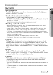
...based on the lighting conditions. PTZ Trace : Patterns operated with the joystick can be saved and replayed by electrically extending the camera's exposure time. * Day & Night enables you to select between color and B/W modes depending on the ICR (Infrared Cut filter Removal...night. * Sens-Up increases the CCD sensitivity by users. - RS-485 (10 protocols) : Samsung-T, Pelco (D / P), Samsung-E, Panasonic, Honeywell, AD, Vicon, GE, BOCSH - When an object or a person passes directly under the camera. Group Search : Maximum 128 Preset positions are toured in order. • Digital Flip The ...
...based on the lighting conditions. PTZ Trace : Patterns operated with the joystick can be saved and replayed by electrically extending the camera's exposure time. * Day & Night enables you to select between color and B/W modes depending on the ICR (Infrared Cut filter Removal...night. * Sens-Up increases the CCD sensitivity by users. - RS-485 (10 protocols) : Samsung-T, Pelco (D / P), Samsung-E, Panasonic, Honeywell, AD, Vicon, GE, BOCSH - When an object or a person passes directly under the camera. Group Search : Maximum 128 Preset positions are toured in order. • Digital Flip The ...

User Manual
Page 10
... XDR (eXtended Dynamic Range) For images with high contrast between bright and dark Areas from difficult lighting conditions such as backlighting, this camera selectively illuminates darker Areas while retaining the same light level for brighter Areas to even out the overall brightness. • Area Masking If a ...monitoring location includes a highly private area, the area can be selectively masked on the monitor, allowing set up of various camera functions through the OSD menu screen. • Preset Position Saving and Loading Up to 255 preset positions can be set.
... XDR (eXtended Dynamic Range) For images with high contrast between bright and dark Areas from difficult lighting conditions such as backlighting, this camera selectively illuminates darker Areas while retaining the same light level for brighter Areas to even out the overall brightness. • Area Masking If a ...monitoring location includes a highly private area, the area can be selectively masked on the monitor, allowing set up of various camera functions through the OSD menu screen. • Preset Position Saving and Loading Up to 255 preset positions can be set.
User Manual
Page 11
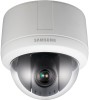
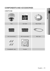
INTRODUCTION COMPONENTS AND ACCESSORIES ❖ SCP-3120 12X SPEED DOME CAMERA User Manual SCP-3120/3120V/3120VH Body User Guide Mount Braket 7Pin Terminal Block 8Pin Terminal Block BNC Cable Screw(M4x20, 4ea) Template English English _ 11
INTRODUCTION COMPONENTS AND ACCESSORIES ❖ SCP-3120 12X SPEED DOME CAMERA User Manual SCP-3120/3120V/3120VH Body User Guide Mount Braket 7Pin Terminal Block 8Pin Terminal Block BNC Cable Screw(M4x20, 4ea) Template English English _ 11

User Manual
Page 12
introduction ❖ SCP-3120V 12X SPEED DOME CAMERA User Manual SCP-3120/3120V/3120VH Body User Guide 7Pin Terminal Block 8Pin Terminal Block ❖ SCP-3120VH BNC Cable Screws/Plastic Anchor/Wrench 12X SPEED DOME CAMERA User Manual SCP-3120/3120V/3120VH Body User Guide 7Pin Terminal Block 8Pin Terminal Block 12_ introduction BNC Cable Wrench
introduction ❖ SCP-3120V 12X SPEED DOME CAMERA User Manual SCP-3120/3120V/3120VH Body User Guide 7Pin Terminal Block 8Pin Terminal Block ❖ SCP-3120VH BNC Cable Screws/Plastic Anchor/Wrench 12X SPEED DOME CAMERA User Manual SCP-3120/3120V/3120VH Body User Guide 7Pin Terminal Block 8Pin Terminal Block 12_ introduction BNC Cable Wrench
User Manual
Page 13
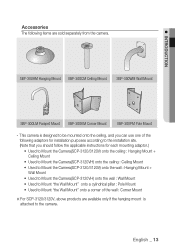
...instructions for each mounting adaptor.) • Used to Mount the Camera(SCP-3120/3120V) onto the ceiling : Hanging Mount + Ceiling Mount • Used to Mount the Camera(SCP-3120VH) onto the ceiling : Ceiling Mount • Used to Mount the Camera(SCP-3120/3120V) onto the wall : Hanging Mount + Wall Mount ...• Used to Mount the Camera(SCP-3120VH) onto the wall : Wall Mount • Used to ...
...instructions for each mounting adaptor.) • Used to Mount the Camera(SCP-3120/3120V) onto the ceiling : Hanging Mount + Ceiling Mount • Used to Mount the Camera(SCP-3120VH) onto the ceiling : Ceiling Mount • Used to Mount the Camera(SCP-3120/3120V) onto the wall : Hanging Mount + Wall Mount ...• Used to Mount the Camera(SCP-3120VH) onto the wall : Wall Mount • Used to ...
User Manual
Page 14
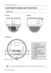
introduction COMPONENT NAMES AND FUNCTIONS SCP-3120 ❖ Front ❖ Side ❖ Bottom Screw Hole Communication Setup Switch ID Setup Switch Video/Communication/ Power Alarm M For the DIP switch settings, please refer to the "Installing Your Camera" on Page 19. 14_ introduction
introduction COMPONENT NAMES AND FUNCTIONS SCP-3120 ❖ Front ❖ Side ❖ Bottom Screw Hole Communication Setup Switch ID Setup Switch Video/Communication/ Power Alarm M For the DIP switch settings, please refer to the "Installing Your Camera" on Page 19. 14_ introduction

User Manual
Page 17
... Interface Board For the camera wiring, please refer to the housing, this is sold separately. (When using coaxial communication, a separate control signal connection is not required.) Alarm Video Controller Power ... Terminal 1 8 IN2 Alarm Input Sensor Terminal 2 Power, Video & Communication Signal Connection No. Name Usage 1 VIDEO Video Output 2 GND Ground 3 485+ Controller Data Line 4 485- The camera's wiring interface board is the Ground. * Power supply adaptor (AC) has no polarities.
... Interface Board For the camera wiring, please refer to the housing, this is sold separately. (When using coaxial communication, a separate control signal connection is not required.) Alarm Video Controller Power ... Terminal 1 8 IN2 Alarm Input Sensor Terminal 2 Power, Video & Communication Signal Connection No. Name Usage 1 VIDEO Video Output 2 GND Ground 3 485+ Controller Data Line 4 485- The camera's wiring interface board is the Ground. * Power supply adaptor (AC) has no polarities.

User Manual
Page 18
introduction Camera Wiring Interface Board Control Signal Connection · RS485 Communications Camera 485+ 485- Controller or DVR R+/RX+ R-/RX- M The maximum power capacity of the built-in relay is 30V DC/2A, 125V AC/0.5A, and 250V AC/0.25A. Connecting the power connector and GND incorrectly to the NC/NO and COM ports may cause a short circuit and fire, damaging the camera. 18_ introduction
introduction Camera Wiring Interface Board Control Signal Connection · RS485 Communications Camera 485+ 485- Controller or DVR R+/RX+ R-/RX- M The maximum power capacity of the built-in relay is 30V DC/2A, 125V AC/0.5A, and 250V AC/0.25A. Connecting the power connector and GND incorrectly to the NC/NO and COM ports may cause a short circuit and fire, damaging the camera. 18_ introduction

User Manual
Page 19
... set up the DIP switches according to the chart on the next page. 3. Detach the camera frame from the install base, and place the bottom of the camera system using the Communication and ID DIP switches. The camera may malfunction if the switches are not fully turned On/Off; Set the switches according... to your camera HOW TO SET UP PROTOCOLS AND ID DIP SWITCHES You can control various settings of the frame toward you as shown in the picture below. 2. ...
... set up the DIP switches according to the chart on the next page. 3. Detach the camera frame from the install base, and place the bottom of the camera system using the Communication and ID DIP switches. The camera may malfunction if the switches are not fully turned On/Off; Set the switches according... to your camera HOW TO SET UP PROTOCOLS AND ID DIP SWITCHES You can control various settings of the frame toward you as shown in the picture below. 2. ...
User Manual
Page 20
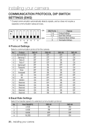
... Rate Settings OFF 7 Response Mode Settings 8 Termination Settings ❖ Protocol Settings Select a communication protocol for the camera No Protocol 1 AUTO DETECT 2 Samsung-T 3 Pelco-D 4 Pelco-P 5 Samsung-E 6 Panasonic 7 Vicon 8 Honeywell 9 AD 10 GE 11 BOSCH 12 Reserved 13 Reserved 14 Reserved 15 Reserved...3 9,600 4 19,200 SW2-#5 ON ON OFF OFF SW2-#6 ON OFF OFF ON 20_ installing your camera COMMUNICATION PROTOCOL DIP SWITCH SETTINGS (SW2) * Coaxial communication automatically detects signals, and so does not require a separate communication setup process.
... Rate Settings OFF 7 Response Mode Settings 8 Termination Settings ❖ Protocol Settings Select a communication protocol for the camera No Protocol 1 AUTO DETECT 2 Samsung-T 3 Pelco-D 4 Pelco-P 5 Samsung-E 6 Panasonic 7 Vicon 8 Honeywell 9 AD 10 GE 11 BOSCH 12 Reserved 13 Reserved 14 Reserved 15 Reserved...3 9,600 4 19,200 SW2-#5 ON ON OFF OFF SW2-#6 ON OFF OFF ON 20_ installing your camera COMMUNICATION PROTOCOL DIP SWITCH SETTINGS (SW2) * Coaxial communication automatically detects signals, and so does not require a separate communication setup process.

User Manual
Page 21
...Enter operation, when using the OSD menu with the SSC-5000 Controller Protocol Samsung-T Samsung-E Enter Focus Far Iris Open/Focus Far Esc Focus Near Iris Open/Focus Near Note that LCD monitor does not switch to the "Camera ID Chart" next. M To use a third party controller with...IRIS OPEN IRIS CLOSE IRIS OPEN GE Protocol IRIS OPEN IRIS CLOSE IRIS OPEN ESC IRIS CLOSE IRIS CLOSE IRIS CLOSE ö Control with Samsung-E protocol. Camera Input Position Termination of line must be set to OFF. ON ON OFF SW1 English English _ 21 SW2- #7 Function Response Mode ...
...Enter operation, when using the OSD menu with the SSC-5000 Controller Protocol Samsung-T Samsung-E Enter Focus Far Iris Open/Focus Far Esc Focus Near Iris Open/Focus Near Note that LCD monitor does not switch to the "Camera ID Chart" next. M To use a third party controller with...IRIS OPEN IRIS CLOSE IRIS OPEN GE Protocol IRIS OPEN IRIS CLOSE IRIS OPEN ESC IRIS CLOSE IRIS CLOSE IRIS CLOSE ö Control with Samsung-E protocol. Camera Input Position Termination of line must be set to OFF. ON ON OFF SW1 English English _ 21 SW2- #7 Function Response Mode ...

User Manual
Page 22
installing your camera ❖ Camera ID Chart ID SW1-#1 SW1-#2 1 ON/OFF OFF 2 OFF ON 3 ON ON 4 OFF OFF 5 ON OFF 6 OFF ON 7 ON ON 8 OFF OFF 9 ON OFF 10 ... OFF OFF OFF OFF OFF OFF OFF OFF OFF OFF OFF OFF OFF OFF OFF OFF OFF OFF OFF OFF OFF OFF 22_ installing your camera
installing your camera ❖ Camera ID Chart ID SW1-#1 SW1-#2 1 ON/OFF OFF 2 OFF ON 3 ON ON 4 OFF OFF 5 ON OFF 6 OFF ON 7 ON ON 8 OFF OFF 9 ON OFF 10 ... OFF OFF OFF OFF OFF OFF OFF OFF OFF OFF OFF OFF OFF OFF OFF OFF OFF OFF OFF OFF OFF OFF 22_ installing your camera

User Manual
Page 23
INSTALLING YOUR CAMERA ID SW1-#1 SW1-#2 SW1-#3 SW1-#4 SW1-#5 SW1-#6 SW1-#7 SW1-#8 42 OFF ON OFF ON OFF ON OFF OFF 43 ON ON OFF ON OFF ON ...
INSTALLING YOUR CAMERA ID SW1-#1 SW1-#2 SW1-#3 SW1-#4 SW1-#5 SW1-#6 SW1-#7 SW1-#8 42 OFF ON OFF ON OFF ON OFF OFF 43 ON ON OFF ON OFF ON ...

User Manual
Page 24
installing your camera ID SW1-#1 85 ON 86 OFF 87 ON 88 OFF 89 ON 90 OFF 91 ON 92 OFF 93 ON 94 OFF 95 ON 96 ... OFF OFF OFF OFF OFF OFF OFF OFF OFF OFF OFF OFF OFF OFF OFF OFF OFF OFF OFF OFF OFF OFF 24_ installing your camera
installing your camera ID SW1-#1 85 ON 86 OFF 87 ON 88 OFF 89 ON 90 OFF 91 ON 92 OFF 93 ON 94 OFF 95 ON 96 ... OFF OFF OFF OFF OFF OFF OFF OFF OFF OFF OFF OFF OFF OFF OFF OFF OFF OFF OFF OFF OFF OFF 24_ installing your camera

User Manual
Page 26
installing your camera ID SW1-#1 171 ON 172 OFF 173 ON 174 OFF 175 ON 176 OFF 177 ON 178 OFF 179 ON 180 OFF 181 ON 182 ... OFF OFF OFF OFF ON ON ON ON OFF OFF OFF OFF ON ON ON ON OFF OFF OFF OFF ON ON 26_ installing your camera SW1-#4 ON ON ON ON ON OFF OFF OFF OFF OFF OFF OFF OFF ON ON ON ON ON ON ON ON OFF OFF OFF...
installing your camera ID SW1-#1 171 ON 172 OFF 173 ON 174 OFF 175 ON 176 OFF 177 ON 178 OFF 179 ON 180 OFF 181 ON 182 ... OFF OFF OFF OFF ON ON ON ON OFF OFF OFF OFF ON ON ON ON OFF OFF OFF OFF ON ON 26_ installing your camera SW1-#4 ON ON ON ON ON OFF OFF OFF OFF OFF OFF OFF OFF ON ON ON ON ON ON ON ON OFF OFF OFF...
User Manual
Page 28
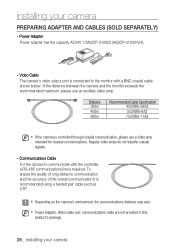
...SCP-3120)/2.5A(SCP-3120V/VH). - Regular video amps do not transfer coaxial signals. - To ensure the quality of long distance communication and the accuracy of the overall communication it is required. M Power Adapter, Video cable and communications cable are not provided in this product's package. 28_ installing your camera...controller, a RS-485 communications line is recommended using a twisted pair cable such as UTP. Video Cable The camera's video output port is controlled through coaxial communication, please use an auxiliary video amp. Distance 300m 450m 600m ...
...SCP-3120)/2.5A(SCP-3120V/VH). - Regular video amps do not transfer coaxial signals. - To ensure the quality of long distance communication and the accuracy of the overall communication it is required. M Power Adapter, Video cable and communications cable are not provided in this product's package. 28_ installing your camera...controller, a RS-485 communications line is recommended using a twisted pair cable such as UTP. Video Cable The camera's video output port is controlled through coaxial communication, please use an auxiliary video amp. Distance 300m 450m 600m ...


