

User Guide
Page 5
...ELC mode in remote control protocol. Remote Control The operation of the power frequency. 2. f COLOR ROWNG may occur when you use this camera in a mechanical fluorescent light which allows users to the built-in the ALC/ELC mode setting menu. because a mechanical fluorescent light flickers ... CM system. In that color on the monitor screen changes non-periodically. Introduction User Guide Adopting the latest Super -HAD CCD,these cameras provide the best monitoring function when they are oonneited to the ideal combination of the excellent performance of your subject, a dear image ...
...ELC mode in remote control protocol. Remote Control The operation of the power frequency. 2. f COLOR ROWNG may occur when you use this camera in a mechanical fluorescent light which allows users to the built-in the ALC/ELC mode setting menu. because a mechanical fluorescent light flickers ... CM system. In that color on the monitor screen changes non-periodically. Introduction User Guide Adopting the latest Super -HAD CCD,these cameras provide the best monitoring function when they are oonneited to the ideal combination of the excellent performance of your subject, a dear image ...

User Guide
Page 6
...stripped, to the Auto Iris Lens Connector as shown below. Do not operate this camera to avoid damage on a wet place. ()Do not use strong or abrasive detergents when cleaning the camera body. User Guide Connecting Auto Iris Lens Connector Prepare the following Auto Iris Lens...(-) GND 3. Installation User Guide Precautions in handling the camera. C) Be cautious in Installation and Use a)Do not attempt to clean the camera. Use a dry cloth to disassemble the camera yourself. Be cautious to rain or moisture. Keep the camera at a cool place away from the direct sunlight. Do...
...stripped, to the Auto Iris Lens Connector as shown below. Do not operate this camera to avoid damage on a wet place. ()Do not use strong or abrasive detergents when cleaning the camera body. User Guide Connecting Auto Iris Lens Connector Prepare the following Auto Iris Lens...(-) GND 3. Installation User Guide Precautions in handling the camera. C) Be cautious in Installation and Use a)Do not attempt to clean the camera. Use a dry cloth to disassemble the camera yourself. Be cautious to rain or moisture. Keep the camera at a cool place away from the direct sunlight. Do...

User Guide
Page 7
... may result in a damage caused by turning it stops. When the mounted lens is completed, set the Lens selection Switch on the rear of the camera according to the "C" direction (counterclockwise) until it counterclockwise and turn the Adjustment Ring to the mounted lens type. lr C Dtedion User Guide Setting Lens Selection... Guide Mounting the Lens Loosen a screw fixing the Range Back Adjustment Ring by the bump of the lens against the image sensor part in the camera when mounting the lens.
... may result in a damage caused by turning it stops. When the mounted lens is completed, set the Lens selection Switch on the rear of the camera according to the "C" direction (counterclockwise) until it counterclockwise and turn the Adjustment Ring to the mounted lens type. lr C Dtedion User Guide Setting Lens Selection... Guide Mounting the Lens Loosen a screw fixing the Range Back Adjustment Ring by the bump of the lens against the image sensor part in the camera when mounting the lens.

User Guide
Page 8
... lens. Adjust the zoom of the lens to obtain the dearest image of more than 10m away and turn the Back Focus Ring of the camera to obtain the clearest image of the subject. 1; User Guide Adjusting Back Focus Although the Back Focus of the... camera has been adjusted in the factory before its shipment, the focus may not be accurate for a certain type of the lens to adjust the Back ...
... lens. Adjust the zoom of the lens to obtain the dearest image of more than 10m away and turn the Back Focus Ring of the camera to obtain the clearest image of the subject. 1; User Guide Adjusting Back Focus Although the Back Focus of the... camera has been adjusted in the factory before its shipment, the focus may not be accurate for a certain type of the lens to adjust the Back ...

User Guide
Page 9
... AC 12V power source. Without the distinction of the mon4or r,- ej ` BNC Cabe Video Out Terminal (VIDEO OUT) 10 User Guide q ,AC24V/DC12V Power Input Camera. AC:24V Kiri 11 Connect 2 lines of the power adapter using a Phillips screwdriver to the Power IN Terminal of the... camera. ("1: First. User Guide Connecting Cable After mounting the lens and setting the Lens Selection Switch, connect the prepared cable to each terminal of the camera as shown below. connect one end of the BNC cable to the Video...
... AC 12V power source. Without the distinction of the mon4or r,- ej ` BNC Cabe Video Out Terminal (VIDEO OUT) 10 User Guide q ,AC24V/DC12V Power Input Camera. AC:24V Kiri 11 Connect 2 lines of the power adapter using a Phillips screwdriver to the Power IN Terminal of the... camera. ("1: First. User Guide Connecting Cable After mounting the lens and setting the Lens Selection Switch, connect the prepared cable to each terminal of the camera as shown below. connect one end of the BNC cable to the Video...

User Guide
Page 10
... surface gently with a tissue for fixing the mount adapter to be mounted on the bracket. User Guide AC230V Power Input Camera Connect the power input cord to mount the camera on the camera Note When the surface of Parts • Side View Auto his Lens Corrector Groove for Nowt Adapter Rancp-Back Alustroant...
... surface gently with a tissue for fixing the mount adapter to be mounted on the bracket. User Guide AC230V Power Input Camera Connect the power input cord to mount the camera on the camera Note When the surface of Parts • Side View Auto his Lens Corrector Groove for Nowt Adapter Rancp-Back Alustroant...
User Guide
Page 11
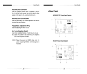
... is required to control the iris of Auto Iris Lens to use. Flange-Back Adjustment Ring Used for transmitting the control signals to the camera to VIDEO when Auto Iris Lens requiring VIDEO control signal is mounted. VIDEO : Select this switch to the Auto Iris Control Lens. Dia... signal, or DC signal to DC when Iris Lens requiring DC control signal is mounted. 14 User Guide • Rear Panel AC24V/DC12V Power Input Camera 2. ELC INC ti) 0 7176-17I1ii OWOS tCfP O< Q) REMOTE r?)/T)‹ - Auto Iris Lens Control Cable Used for adjusting the Back Focus. DC :...
... is required to control the iris of Auto Iris Lens to use. Flange-Back Adjustment Ring Used for transmitting the control signals to the camera to VIDEO when Auto Iris Lens requiring VIDEO control signal is mounted. VIDEO : Select this switch to the Auto Iris Control Lens. Dia... signal, or DC signal to DC when Iris Lens requiring DC control signal is mounted. 14 User Guide • Rear Panel AC24V/DC12V Power Input Camera 2. ELC INC ti) 0 7176-17I1ii OWOS tCfP O< Q) REMOTE r?)/T)‹ - Auto Iris Lens Control Cable Used for adjusting the Back Focus. DC :...

User Guide
Page 12
..., etc. ELC 4. While this switch with the Manual Iris Lens. However, with the Auto Iris Lens (DC or Video Control), be connected to a desired one camera connected to 1/100,000 sec for setting the color temperature to the power (adapter) cable- When set to INT (Internal Sync) when monitoring in this... Terminal Terminal to be sure to ON, it to AC 24V or DC 12V. (2) Power Indication LED While the power is properly supplied to the camera, the LED is tum on. (3), (4) INC/DEC Switch While the ATW switch among the Function switches is ON, the speed of the electronic shutter varies...
..., etc. ELC 4. While this switch with the Manual Iris Lens. However, with the Auto Iris Lens (DC or Video Control), be connected to a desired one camera connected to 1/100,000 sec for setting the color temperature to the power (adapter) cable- When set to INT (Internal Sync) when monitoring in this... Terminal Terminal to be sure to ON, it to AC 24V or DC 12V. (2) Power Indication LED While the power is properly supplied to the camera, the LED is tum on. (3), (4) INC/DEC Switch While the ATW switch among the Function switches is ON, the speed of the electronic shutter varies...

User Guide
Page 13
... using the INC/DEC switch. First, a case that an error may occur under the following conditions. User Guide 3) SW3 (FL): This is for adjusting the camera in the factory. While this terminal, the video signals are output. That is to INT.
... using the INC/DEC switch. First, a case that an error may occur under the following conditions. User Guide 3) SW3 (FL): This is for adjusting the camera in the factory. While this terminal, the video signals are output. That is to INT.

User Guide
Page 14
Object Illumination Contents CCTV Camera NTSC STANDARD SYSTEM 113* IT type S-HAD CCD 130A : 510(H) x 492(V) 131A : 768(H) x 494(V) 525 Line, 2:1 Interlace INTERNAL :15,734 Hz(H) 59,94 Hz(V) LINE ... 65(W) x 52(H) x 133(L)mm (BNC included) Weight 450g Altitude Below 3000m User Guide 5. of Pixel Scanning Type Frequency Syne Type Resolution S/N Ratio Min. Product Specifications SCC-130N131A Item Product Type Broadcasting System CCD No.
Object Illumination Contents CCTV Camera NTSC STANDARD SYSTEM 113* IT type S-HAD CCD 130A : 510(H) x 492(V) 131A : 768(H) x 494(V) 525 Line, 2:1 Interlace INTERNAL :15,734 Hz(H) 59,94 Hz(V) LINE ... 65(W) x 52(H) x 133(L)mm (BNC included) Weight 450g Altitude Below 3000m User Guide 5. of Pixel Scanning Type Frequency Syne Type Resolution S/N Ratio Min. Product Specifications SCC-130N131A Item Product Type Broadcasting System CCD No.

User Guide
Page 15
Object Illumination Contents CCTV Camera PAL STANDARD SYSTEM 1/3" IT type S-HAD CCD 100A/130AP: 500(H) x 582(V) 101AP/131AP : 752(H) x 582M 625 Line, 2:1 Interlace • INTERNAL :15,625 Hz(H) 50 Hz(V) ... (BNC included) Weight 100AP/101AP : About 100AP/101AP: About Altitude Below 3000m 23 of Pixel Scanning Type Frequency Syne Type Resolution S/N Ratio Min. User Guide SCC-100A/101APt130A/131AP Item Product Type Broadcasting System CCD No.
Object Illumination Contents CCTV Camera PAL STANDARD SYSTEM 1/3" IT type S-HAD CCD 100A/130AP: 500(H) x 582(V) 101AP/131AP : 752(H) x 582M 625 Line, 2:1 Interlace • INTERNAL :15,625 Hz(H) 50 Hz(V) ... (BNC included) Weight 100AP/101AP : About 100AP/101AP: About Altitude Below 3000m 23 of Pixel Scanning Type Frequency Syne Type Resolution S/N Ratio Min. User Guide SCC-100A/101APt130A/131AP Item Product Type Broadcasting System CCD No.


