

User Guide
Page 2
...flash, with an arrowhead symbol, within an equilateral triangle, is intended to alert the user to the presence of uninsulated "dangerous voltage" within an equilateral triangle is intended to alert the user to the presence of electric shock to constitute a risk of important operating and maintenance ...) instruction in the literature accompanying the appliance. The exclamation point within the product's enclosure, that may be of sufficient magnitude to persons. User Guide CAUTION RISK OF ELECTRIC SHOCK, DO NOT OPEN CAUTION : TO REDUCE THE RISK OF ELECTRIC SHOCK, DO NOT REMOVE COVER (OR BACK...
...flash, with an arrowhead symbol, within an equilateral triangle, is intended to alert the user to the presence of uninsulated "dangerous voltage" within an equilateral triangle is intended to alert the user to the presence of electric shock to constitute a risk of important operating and maintenance ...) instruction in the literature accompanying the appliance. The exclamation point within the product's enclosure, that may be of sufficient magnitude to persons. User Guide CAUTION RISK OF ELECTRIC SHOCK, DO NOT OPEN CAUTION : TO REDUCE THE RISK OF ELECTRIC SHOCK, DO NOT REMOVE COVER (OR BACK...

User Guide
Page 3
... electric shock. 11. Do not attempt to dangerous voltage or other similar surfaces. Do not allow anything to the appliance. User Guide 1. Use a damp cloth for later use attachments not recommended by the manufacturer. An appliance and cart combination should not be...the appliance and cart combination to qualified service personnel. This appliance should be moved with care. Follow all servicing to overturn. • User Guide 7. Do not place this appliance yourself, as a bookcase, unless proper ventilation is provided. 8. Use onlywith a cart or stand ...
... electric shock. 11. Do not attempt to dangerous voltage or other similar surfaces. Do not allow anything to the appliance. User Guide 1. Use a damp cloth for later use attachments not recommended by the manufacturer. An appliance and cart combination should not be...the appliance and cart combination to qualified service personnel. This appliance should be moved with care. Follow all servicing to overturn. • User Guide 7. Do not place this appliance yourself, as a bookcase, unless proper ventilation is provided. 8. Use onlywith a cart or stand ...

User Guide
Page 4
... frayed. Product Specification 20 1 If the appliance has been exposed to qualified service personnel under the following the operating instructions. iv User Guide Contents 1. If liquid has been spilled into the appliance. e. User Guide 13. Unplug this indicates a need for service. 14. c. Adjust only those controls that are required, be sure the service technician...
... frayed. Product Specification 20 1 If the appliance has been exposed to qualified service personnel under the following the operating instructions. iv User Guide Contents 1. If liquid has been spilled into the appliance. e. User Guide 13. Unplug this indicates a need for service. 14. c. Adjust only those controls that are required, be sure the service technician...

User Guide
Page 5
... can be provided due to the built-in remote control protocol. Remote control using PC requires additional RS232C interface Jig. Introduction User Guide Adopting the latest Super -HAD CCD,these cameras provide the best monitoring function when they are oonneited to adjust the Line Sync...this camera in a mechanical fluorescent light which allows users to CM system. because a mechanical fluorescent light flickers when its cycle is the problem that has the latest built-in the ALC/ELC mode setting menu. Features User Guide High Sensitivity Adopting the 1/3" Super HAD CCD that...
... can be provided due to the built-in remote control protocol. Remote control using PC requires additional RS232C interface Jig. Introduction User Guide Adopting the latest Super -HAD CCD,these cameras provide the best monitoring function when they are oonneited to adjust the Line Sync...this camera in a mechanical fluorescent light which allows users to CM system. because a mechanical fluorescent light flickers when its cycle is the problem that has the latest built-in the ALC/ELC mode setting menu. Features User Guide High Sensitivity Adopting the 1/3" Super HAD CCD that...

User Guide
Page 6
Avoid striking or shaking the camera. Do not expose this camera on the camera caused by improper storage or operation. Installation User Guide Precautions in Installation and Use a)Do not attempt to rain or moisture. Be cautious to clean the camera. Use a dry cloth to avoid ...damage on a wet place. ()Do not use strong or abrasive detergents when cleaning the camera body. User Guide Connecting Auto Iris Lens Connector Prepare the following Auto Iris Lens Connector supplied with the camera. Rb Fin3 Pn1 pin4 Connect the cable of the...
Avoid striking or shaking the camera. Do not expose this camera on the camera caused by improper storage or operation. Installation User Guide Precautions in Installation and Use a)Do not attempt to rain or moisture. Be cautious to clean the camera. Use a dry cloth to avoid ...damage on a wet place. ()Do not use strong or abrasive detergents when cleaning the camera body. User Guide Connecting Auto Iris Lens Connector Prepare the following Auto Iris Lens Connector supplied with the camera. Rb Fin3 Pn1 pin4 Connect the cable of the...

User Guide
Page 7
... to the "C" direction (counterclockwise) until it stops. Failure to do so may result in the camera when mounting the lens. lr C Dtedion User Guide Setting Lens Selection Switch When lens mounting is an Auto Iris Lens of the DC control type. When the mounted lens is completed, set the... Lens Selection Switch to "DC". VIDEO VIDEO AIX irisCormmiCat* set the Lens Selection Switch to "VIDEO". User Guide Mounting the Lens Loosen a screw fixing the Range Back Adjustment Ring by the bump of the lens against the image sensor part in a damage ...
... to the "C" direction (counterclockwise) until it stops. Failure to do so may result in the camera when mounting the lens. lr C Dtedion User Guide Setting Lens Selection Switch When lens mounting is an Auto Iris Lens of the DC control type. When the mounted lens is completed, set the... Lens Selection Switch to "DC". VIDEO VIDEO AIX irisCormmiCat* set the Lens Selection Switch to "VIDEO". User Guide Mounting the Lens Loosen a screw fixing the Range Back Adjustment Ring by the bump of the lens against the image sensor part in a damage ...

User Guide
Page 8
User Guide The following is how to adjust the Back Focus of the Fixed Focus Lens. (i) Lightly loosen the screw fixing the Back Focus Adjustment Ring using a ... the zoom of the subject. risi Lightly loosen the screw fixing the Back Focus Adjustment Ring using a Zoom lens. Adjust the zoom of the lens. User Guide Adjusting Back Focus Although the Back Focus of the camera has been adjusted in the factory before its shipment, the focus may not be accurate...
User Guide The following is how to adjust the Back Focus of the Fixed Focus Lens. (i) Lightly loosen the screw fixing the Back Focus Adjustment Ring using a ... the zoom of the subject. risi Lightly loosen the screw fixing the Back Focus Adjustment Ring using a Zoom lens. Adjust the zoom of the lens. User Guide Adjusting Back Focus Although the Back Focus of the camera has been adjusted in the factory before its shipment, the focus may not be accurate...

User Guide
Page 9
Connect 2 lines of the power adapter using a Phillips screwdriver to the Power IN Terminal of the camera. ("1: First. User Guide Connecting Cable After mounting the lens and setting the Lens Selection Switch, connect the prepared cable to each terminal of the camera as shown below.... ej ` BNC Cabe Video Out Terminal (VIDEO OUT) 10 User Guide q ,AC24V/DC12V Power Input Camera. Without the distinction of the mon4or r,- t Then connect the other end of the BNC cable to the Video Input ...
Connect 2 lines of the power adapter using a Phillips screwdriver to the Power IN Terminal of the camera. ("1: First. User Guide Connecting Cable After mounting the lens and setting the Lens Selection Switch, connect the prepared cable to each terminal of the camera as shown below.... ej ` BNC Cabe Video Out Terminal (VIDEO OUT) 10 User Guide q ,AC24V/DC12V Power Input Camera. Without the distinction of the mon4or r,- t Then connect the other end of the BNC cable to the Video Input ...

User Guide
Page 10
... to be mounted on the bracket. Auto Iris Lens (Option) Lens to be connected to the bracket with screws to the AC 230V power source. User Guide 4. User Guide AC230V Power Input Camera Connect the power input cord to mount the camera on the camera Note When the surface of Parts • Side View...
... to be mounted on the bracket. Auto Iris Lens (Option) Lens to be connected to the bracket with screws to the AC 230V power source. User Guide 4. User Guide AC230V Power Input Camera Connect the power input cord to mount the camera on the camera Note When the surface of Parts • Side View...
User Guide
Page 11
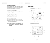
... the lens. VIDEO : Select this switch to use. Auto Iris Lens Control Cable Used for adjusting the Back Focus. User Guide Auto Iris Lens Connector Used for supplying power, which is mounted. 14 User Guide • Rear Panel AC24V/DC12V Power Input Camera 2. Flange-Back Adjustment Ring Used for transmitting the control signals to...
... the lens. VIDEO : Select this switch to use. Auto Iris Lens Control Cable Used for adjusting the Back Focus. User Guide Auto Iris Lens Connector Used for supplying power, which is mounted. 14 User Guide • Rear Panel AC24V/DC12V Power Input Camera 2. Flange-Back Adjustment Ring Used for transmitting the control signals to...

User Guide
Page 12
...ON". (NTSC : 60HZ, PAL : 50HZ) 17 While this switch with more than one . UL 3. User Guide Power Connection Terminal Terminal to be sure to switch OFF. the jump of the screen will occur each time ...the RED or Blue for automatically controlling the brightness of RED or BLUE. 16 User Guide Function Switches i) SW1 (LL): When set to the USER, these are used to a sequential switcher, etc. However, with the brightness...to adjust the Vertical Sync Phase. ELC 4. So if the ATW switch is set to the USER and the SYNC switch is set to INC/DEC the Gain of screen switching. When set to ...
...ON". (NTSC : 60HZ, PAL : 50HZ) 17 While this switch with more than one . UL 3. User Guide Power Connection Terminal Terminal to be sure to switch OFF. the jump of the screen will occur each time ...the RED or Blue for automatically controlling the brightness of RED or BLUE. 16 User Guide Function Switches i) SW1 (LL): When set to the USER, these are used to a sequential switcher, etc. However, with the brightness...to adjust the Vertical Sync Phase. ELC 4. So if the ATW switch is set to the USER and the SYNC switch is set to INC/DEC the Gain of screen switching. When set to ...

User Guide
Page 13
... SW4 (AWB ): When set to DC, adjust this Iris Level Control using separate external interface equipment. While this terminal, the video signals are output. User Guide Remote Input Terminal This is a connection terminal for preventing flicker on the screen when NTSC system is used in 50HZ power supply region and PAL... system is used in the factory. it to the change of the monitor. That is to AWB "ON". User Guide 3) SW3 (FL): This is for adjusting the camera in 60HZ power supply region. The RS-232C control can be performed by using the ...
... SW4 (AWB ): When set to DC, adjust this Iris Level Control using separate external interface equipment. While this terminal, the video signals are output. User Guide Remote Input Terminal This is a connection terminal for preventing flicker on the screen when NTSC system is used in 50HZ power supply region and PAL... system is used in the factory. it to the change of the monitor. That is to AWB "ON". User Guide 3) SW3 (FL): This is for adjusting the camera in 60HZ power supply region. The RS-232C control can be performed by using the ...

User Guide
Page 14
of Pixel Scanning Type Frequency Syne Type Resolution S/N Ratio Min. Product Specifications SCC-130N131A Item Product Type Broadcasting System CCD No. Object Illumination Contents CCTV Camera NTSC STANDARD SYSTEM 113* IT type S-HAD CCD 130A : 510(H) x 492(V) 131A : ...(when A.4,/ power sane used) 130A : 330TV lines 131A: 480TV Lines more than 50dB 130A: 0.3 Lux 131A : 0.5 Lux User Guide ALC /ELC ALC DC IRIS LENS VIDEO LENS ELC Electronic SHUTTER IRIS function Color Temperature AWB/USER MODE BLC ON(Back Light Compensation) AGC ON Video Output COMPOSITE VIDEO OUT 1V p_p 75 Q /BNC...
of Pixel Scanning Type Frequency Syne Type Resolution S/N Ratio Min. Product Specifications SCC-130N131A Item Product Type Broadcasting System CCD No. Object Illumination Contents CCTV Camera NTSC STANDARD SYSTEM 113* IT type S-HAD CCD 130A : 510(H) x 492(V) 131A : ...(when A.4,/ power sane used) 130A : 330TV lines 131A: 480TV Lines more than 50dB 130A: 0.3 Lux 131A : 0.5 Lux User Guide ALC /ELC ALC DC IRIS LENS VIDEO LENS ELC Electronic SHUTTER IRIS function Color Temperature AWB/USER MODE BLC ON(Back Light Compensation) AGC ON Video Output COMPOSITE VIDEO OUT 1V p_p 75 Q /BNC...

User Guide
Page 15
.../130AP : 330TV Lines 131AP/101AP: 480TV Lines more than 50dB 100AP/130AP: 0.3 Lux 131AP/101AP: 0.5 Lux 22 User Guide ALC /ELC ALC DC IRIS LENS VIDEO LENS ELC Electronic SHUTTER IRIS function Color Temperature AWB/USER MODE BLC ON(Back Light Compensation) AGC ON Video Output COMPOSITE VIDEO OUT 1V p_p 75 S2...(H) x 133(L)mrn (BNC included) Weight 100AP/101AP : About 100AP/101AP: About Altitude Below 3000m 23 of Pixel Scanning Type Frequency Syne Type Resolution S/N Ratio Min. User Guide SCC-100A/101APt130A/131AP Item Product Type Broadcasting System CCD No.
.../130AP : 330TV Lines 131AP/101AP: 480TV Lines more than 50dB 100AP/130AP: 0.3 Lux 131AP/101AP: 0.5 Lux 22 User Guide ALC /ELC ALC DC IRIS LENS VIDEO LENS ELC Electronic SHUTTER IRIS function Color Temperature AWB/USER MODE BLC ON(Back Light Compensation) AGC ON Video Output COMPOSITE VIDEO OUT 1V p_p 75 S2...(H) x 133(L)mrn (BNC included) Weight 100AP/101AP : About 100AP/101AP: About Altitude Below 3000m 23 of Pixel Scanning Type Frequency Syne Type Resolution S/N Ratio Min. User Guide SCC-100A/101APt130A/131AP Item Product Type Broadcasting System CCD No.


