User Manual (ENGLISH)
Page 2
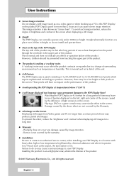
.... - English - 2 This is making a 'cracking' noise. Playing a DVD or a game console may cause similar effect to this effect, reduce the 'brightness' and 'contrast' when displaying still images for longer than 2 hours as it operates for more than a certain period of time may cause permanent damage to a change of light emission on the screen. Burn-in the upper part of the product. ◆...
.... - English - 2 This is making a 'cracking' noise. Playing a DVD or a game console may cause similar effect to this effect, reduce the 'brightness' and 'contrast' when displaying still images for longer than 2 hours as it operates for more than a certain period of time may cause permanent damage to a change of light emission on the screen. Burn-in the upper part of the product. ◆...
User Manual (ENGLISH)
Page 4
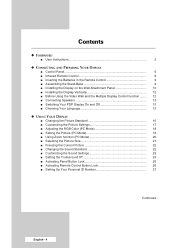
... Remote Control 9 ■ Assembling the Stand-Base 9 ■ Installing the Display on the Wall Attachment Panel 10 ■ Installing the Display Vertically 12 ■ Before Using the Video Wall and the Multiple Display Control function ........ 12 ■ Connecting Speakers 13 ■ Switching Your PDP Display On and Off 15 ■ Choosing Your Language 15 ◆ USING YOUR DISPLAY ■ Changing the Picture Standard 16 ■ Customizing the Picture Settings 17 ■ Adjusting the RGB Color (PC Mode 18 ■ Setting the Picture...
... Remote Control 9 ■ Assembling the Stand-Base 9 ■ Installing the Display on the Wall Attachment Panel 10 ■ Installing the Display Vertically 12 ■ Before Using the Video Wall and the Multiple Display Control function ........ 12 ■ Connecting Speakers 13 ■ Switching Your PDP Display On and Off 15 ■ Choosing Your Language 15 ◆ USING YOUR DISPLAY ■ Changing the Picture Standard 16 ■ Customizing the Picture Settings 17 ■ Adjusting the RGB Color (PC Mode 18 ■ Setting the Picture...

User Manual (ENGLISH)
Page 5
... Screen Burn 30 ■ Setting the Screen Burn Protection Timer 31 ■ Setting the Multiple Screen 32 ■ Displaying the Setting Information 33 ■ Setting and Displaying the Current Time 33 ■ Switching the PDP Display On and Off Automatically 34 ■ Selecting the Fan 36 ■ Viewing the Picture in Picture (PIP 37 ■ Viewing an External Signal Source 38 ◆ ADDITIONAL INFORMATION AND CONNECTIONS ■ Connecting to the Audio/Video Input 39 ■ Connecting to the S-Video Input 40 ■ Connecting...
... Screen Burn 30 ■ Setting the Screen Burn Protection Timer 31 ■ Setting the Multiple Screen 32 ■ Displaying the Setting Information 33 ■ Setting and Displaying the Current Time 33 ■ Switching the PDP Display On and Off Automatically 34 ■ Selecting the Fan 36 ■ Viewing the Picture in Picture (PIP 37 ■ Viewing an External Signal Source 38 ◆ ADDITIONAL INFORMATION AND CONNECTIONS ■ Connecting to the Audio/Video Input 39 ■ Connecting to the S-Video Input 40 ■ Connecting...

User Manual (ENGLISH)
Page 6
... buttons on the remote control. ◆ If the remote control no longer works or you have misplaced it is not operated with source key. MENU Display the on your model. b Power Indicator - Front of the PDP Display Speaker (Optional) Speaker (Optional) a b c a SOURCE - Store your settings in the menu. VOL + - Adjust an option value respectively. (VOL + : Enter to turn the PDP Display on the PDP Display when it , you can use the controls on the panel of the PDP Display. Power Off; Green c Remote Control...
... buttons on the remote control. ◆ If the remote control no longer works or you have misplaced it is not operated with source key. MENU Display the on your model. b Power Indicator - Front of the PDP Display Speaker (Optional) Speaker (Optional) a b c a SOURCE - Store your settings in the menu. VOL + - Adjust an option value respectively. (VOL + : Enter to turn the PDP Display on the PDP Display when it , you can use the controls on the panel of the PDP Display. Power Off; Green c Remote Control...

User Manual (ENGLISH)
Page 7
Rear Panel a) POWER IN Connect the supplied power cord. b) EXT SPEAKER (8Ω) Connect external speakers. d) DVI IN Connect to the video input jack on external devices. f) PC IN2 (BNC) Connect for component. g) RS-232C - e) PC IN1/PC OUT1 - OUT : Used for the MDC function when connecting with RS-232C input of another PDP Display. ➢ For further details about connection, refer to pages 39~42. ➢ Whenever you connect an audio or video system to the documentation...
Rear Panel a) POWER IN Connect the supplied power cord. b) EXT SPEAKER (8Ω) Connect external speakers. d) DVI IN Connect to the video input jack on external devices. f) PC IN2 (BNC) Connect for component. g) RS-232C - e) PC IN1/PC OUT1 - OUT : Used for the MDC function when connecting with RS-232C input of another PDP Display. ➢ For further details about connection, refer to pages 39~42. ➢ Whenever you connect an audio or video system to the documentation...

User Manual (ENGLISH)
Page 8
... SELECTION (SOURCE) PDP DISPLAY OFF PICTURE STILL NEXT CHANNEL EXTERNAL INPUT SELECTION PREVIOUS CHANNEL INFORMATION DISPLAY EXIT FROM ANY DISPLAY CONFIRM YOUR CHOICE (STORE OR ENTER) SOUND EFFECT SELECTION PICTURE SIZE MULTIPLE DISPLAY CONTROL SCREEN EFFECT SELECTION (BURNING PROTECTION) ➢ The performance of the remote control may be affected by bright light. English - 8 PIP ACTIVATION OR DEACTIVATION (PIP) - Infrared Remote Control PDP DISPLAY ON DIRECT CHANNEL SELECTION NOT AVAILABLE VOLUME INCREASE TEMPORARY SOUND SWITCH-OFF VOLUME DECREASE SETTING THE TIMER MENU DISPLAY MOVE...
... SELECTION (SOURCE) PDP DISPLAY OFF PICTURE STILL NEXT CHANNEL EXTERNAL INPUT SELECTION PREVIOUS CHANNEL INFORMATION DISPLAY EXIT FROM ANY DISPLAY CONFIRM YOUR CHOICE (STORE OR ENTER) SOUND EFFECT SELECTION PICTURE SIZE MULTIPLE DISPLAY CONTROL SCREEN EFFECT SELECTION (BURNING PROTECTION) ➢ The performance of the remote control may be affected by bright light. English - 8 PIP ACTIVATION OR DEACTIVATION (PIP) - Infrared Remote Control PDP DISPLAY ON DIRECT CHANNEL SELECTION NOT AVAILABLE VOLUME INCREASE TEMPORARY SOUND SWITCH-OFF VOLUME DECREASE SETTING THE TIMER MENU DISPLAY MOVE...

User Manual (ENGLISH)
Page 11
... back of the product to the bracket. To mount the product on the wall bracket ◆ The shape of the product may not stay in place after installation. 3 Tighten the 4 screws in step 2 (plastic hanger 4 Remove safety pin (#) and insert the 4 product + screw ) to the rear holes of the product. Wall Bracket Wall 1 Fix the product to the wall bracket. 2 Hold the product at the...
... back of the product to the bracket. To mount the product on the wall bracket ◆ The shape of the product may not stay in place after installation. 3 Tighten the 4 screws in step 2 (plastic hanger 4 Remove safety pin (#) and insert the 4 product + screw ) to the rear holes of the product. Wall Bracket Wall 1 Fix the product to the wall bracket. 2 Hold the product at the...
User Manual (ENGLISH)
Page 12
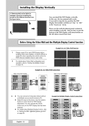
... the ID for Multiple Display Control connections English - 12 Please use the wall attachment panel exclusively when installing vertically. Example for 2x2 Video Wall function Rear of the PDP Display Example for 2x2 Video Wall connections Rear of the PDP Display ② ① ➢ ◆ You can connect a Composite (Video) without a distributor as you have to put the bottom of the PDP Display with menu buttons on the menu. You can install the PDP Display vertically. It may be liable...
... the ID for Multiple Display Control connections English - 12 Please use the wall attachment panel exclusively when installing vertically. Example for 2x2 Video Wall function Rear of the PDP Display Example for 2x2 Video Wall connections Rear of the PDP Display ② ① ➢ ◆ You can connect a Composite (Video) without a distributor as you have to put the bottom of the PDP Display with menu buttons on the menu. You can install the PDP Display vertically. It may be liable...
User Manual (ENGLISH)
Page 19
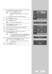
...(s). 7 Press the ENTER ( ) button. 8 Press the MENU ( ) button. Result: The previously adjusted settings will automatically return to exit. Return English - 19 Press the ENTER ( ) button. 10 Adjust the position by pressing the ... The settings are automatically reset. or † button to be reset to the factory defaults. 14 Press the EXIT button to the previous picture. 13 To return the factory defaults, select Image Reset by pressing the or...
...(s). 7 Press the ENTER ( ) button. 8 Press the MENU ( ) button. Result: The previously adjusted settings will automatically return to exit. Return English - 19 Press the ENTER ( ) button. 10 Adjust the position by pressing the ... The settings are automatically reset. or † button to be reset to the factory defaults. 14 Press the EXIT button to the previous picture. 13 To return the factory defaults, select Image Reset by pressing the or...
User Manual (ENGLISH)
Page 25
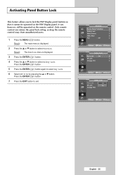
... release the panel lock setting, so keep the remote control away from unauthorized users. 1 Press the MENU ( ) button. Press the ENTER ( ) button. 5 Press the ENTER ( ) button again to lock the PDP Display panel buttons so that it cannot be operated via the PDP Display panel. Activating Panel Button Lock This feature allows you to select Key Lock. 6 Select Off or On by pressing the ▲ or ▼ button. Result: The Function menu is displayed. 2 Press...
... release the panel lock setting, so keep the remote control away from unauthorized users. 1 Press the MENU ( ) button. Press the ENTER ( ) button. 5 Press the ENTER ( ) button again to lock the PDP Display panel buttons so that it cannot be operated via the PDP Display panel. Activating Panel Button Lock This feature allows you to select Key Lock. 6 Select Off or On by pressing the ▲ or ▼ button. Result: The Function menu is displayed. 2 Press...
User Manual (ENGLISH)
Page 28
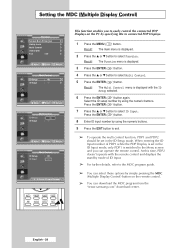
... Multi Control menu is displayed. 3 Press the ENTER ( ) button. 4 Press the ▲ or ▼ button to connected PDP Displays. 1 Press the MENU ( ) button. Press the ENTER ( ) button. 8 Enter ID input number by using the numeric buttons. At this time, PDP2 doesn't operate with the ID Setup selected. 6 Press the ENTER ( ) button again. English - 28 Result: The Function menu is displayed with the remote control and displays the standby mode of PDP1 while the PDP Display is set in...
... Multi Control menu is displayed. 3 Press the ENTER ( ) button. 4 Press the ▲ or ▼ button to connected PDP Displays. 1 Press the MENU ( ) button. Press the ENTER ( ) button. 8 Enter ID input number by using the numeric buttons. At this time, PDP2 doesn't operate with the ID Setup selected. 6 Press the ENTER ( ) button again. English - 28 Result: The Function menu is displayed with the remote control and displays the standby mode of PDP1 while the PDP Display is set in...
User Manual (ENGLISH)
Page 32
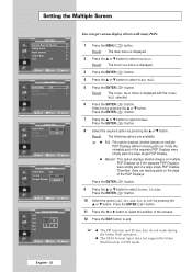
...; The PIP function and Picture Size do not work during the Video Wall operation. ◆ The VESA Format input does not support the Video Wall function in DVI mode. Result: The following options are missing parts on multiple PDP Displays as if only the viewable part of the separate PDP Displays were simply part of a large single PDP Display. ◆ Natural : This option displays divided images on the edge of the PDP Displays. Press the ENTER ( ) button. 11...
...; The PIP function and Picture Size do not work during the Video Wall operation. ◆ The VESA Format input does not support the Video Wall function in DVI mode. Result: The following options are missing parts on multiple PDP Displays as if only the viewable part of the separate PDP Displays were simply part of a large single PDP Display. ◆ Natural : This option displays divided images on the edge of the PDP Displays. Press the ENTER ( ) button. 11...
User Manual (ENGLISH)
Page 37
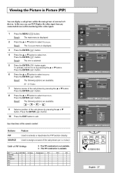
... - Buttons PIP SOURCE Feature Used to select Source. Viewing the Picture in Picture (PIP) You can PDP Display the video input from any connected devices while monitoring other video inputs. 1 Press the MENU ( ) button. In this way you can display a sub picture within the main picture of the sub picture by pressing the ... Result: The PIP is available. Result: The following options are available. Press the ENTER ( ) button. 10 Press the EXIT button to assign a source of PIP Settings...
... - Buttons PIP SOURCE Feature Used to select Source. Viewing the Picture in Picture (PIP) You can PDP Display the video input from any connected devices while monitoring other video inputs. 1 Press the MENU ( ) button. In this way you can display a sub picture within the main picture of the sub picture by pressing the ... Result: The PIP is available. Result: The following options are available. Press the ENTER ( ) button. 10 Press the EXIT button to assign a source of PIP Settings...
User Manual (ENGLISH)
Page 38
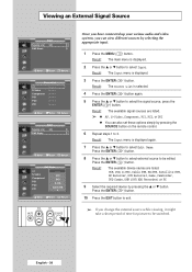
... PC1 PC2 DVI : - - - -VCR : - - - -DVD :---- Result: The main menu is displayed. 3 Press the ENTER ( ) button. Result: The Input menu is selected. 4 Press the ENTER ( ) button again. 5 Press the ... Press the ENTER ( ) button. Cable STB :---- † Move Enter Return Once you have connected up your various audio and video systems, you change the external source while viewing, it might take a short period of time for picture to be switched. Press the...
... PC1 PC2 DVI : - - - -VCR : - - - -DVD :---- Result: The main menu is displayed. 3 Press the ENTER ( ) button. Result: The Input menu is selected. 4 Press the ENTER ( ) button again. 5 Press the ... Press the ENTER ( ) button. Cable STB :---- † Move Enter Return Once you have connected up your various audio and video systems, you change the external source while viewing, it might take a short period of time for picture to be switched. Press the...
User Manual (ENGLISH)
Page 39
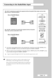
... the signal source is AV. ☛ Whenever you connect an audio or video system to your equipment for detailed connection instructions and associated safety precautions. English - 39 Rear of the PDP Display (Input) VCR ① DVD Decoder / Video game device The "AV OUT" connectors are used for the equipment with an Composite Video input, such as video game devices or video disc players. Connecting to the Audio/Video Input The "AV IN" connectors are used for...
... the signal source is AV. ☛ Whenever you connect an audio or video system to your equipment for detailed connection instructions and associated safety precautions. English - 39 Rear of the PDP Display (Input) VCR ① DVD Decoder / Video game device The "AV OUT" connectors are used for the equipment with an Composite Video input, such as video game devices or video disc players. Connecting to the Audio/Video Input The "AV IN" connectors are used for...
User Manual (ENGLISH)
Page 40
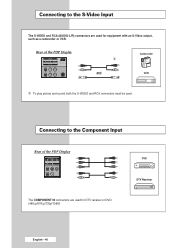
Connecting to the Component Input Rear of the PDP Display Camcorder ① and VCR ① To play picture and sound, both the S-VIDEO and RCA connectors must be used. Connecting to the S-Video Input The S-VIDEO and RCA (AUDIO-L/R) connectors are used for DTV receiver or DVD. (480i,p/576i,p/720p/1080i) DTV Receiver English - 40 Rear of the PDP Display DVD The COMPONENT IN connectors are used for equipment with an S-Video output, such as a camcorder or VCR.
Connecting to the Component Input Rear of the PDP Display Camcorder ① and VCR ① To play picture and sound, both the S-VIDEO and RCA connectors must be used. Connecting to the S-Video Input The S-VIDEO and RCA (AUDIO-L/R) connectors are used for DTV receiver or DVD. (480i,p/576i,p/720p/1080i) DTV Receiver English - 40 Rear of the PDP Display DVD The COMPONENT IN connectors are used for equipment with an S-Video output, such as a camcorder or VCR.
User Manual (ENGLISH)
Page 41
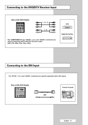
Rear of the PDP Display Y / PB / PR L / R The "COMPONENT IN" (or "Y/PB/PR" (video) and "AUDIO") connectors are used for equipment with a DVD/ DTV Receiver output. (480i, 576i, 480p, 576p, 720p, 1080i) DVD Digital Set-Top Box Connecting to the DVI Input The "DVI IN" (video) and "AUDIO" connectors are used for equipment with a DVI output. Connecting to the DVD/DTV Receiver Input Rear of the PDP Display and Personal Computer English - 41
Rear of the PDP Display Y / PB / PR L / R The "COMPONENT IN" (or "Y/PB/PR" (video) and "AUDIO") connectors are used for equipment with a DVD/ DTV Receiver output. (480i, 576i, 480p, 576p, 720p, 1080i) DVD Digital Set-Top Box Connecting to the DVI Input The "DVI IN" (video) and "AUDIO" connectors are used for equipment with a DVI output. Connecting to the DVD/DTV Receiver Input Rear of the PDP Display and Personal Computer English - 41
User Manual (ENGLISH)
Page 43
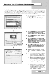
... set the Display Mode with reference to change the Colours settings. 3 Click on your 5 particular version of Windows and your particular video card. English - 43 The Display Properties will be displayed. 2 Click on Properties. A new settings dialog box will be displayed. 4 Click on the Monitor tab, then set -up to 32 bits. ◆ In this moment. 6 Shutdown the PC, and connect it to the PC Input...
... set the Display Mode with reference to change the Colours settings. 3 Click on your 5 particular version of Windows and your particular video card. English - 43 The Display Properties will be displayed. 2 Click on Properties. A new settings dialog box will be displayed. 4 Click on the Monitor tab, then set -up to 32 bits. ◆ In this moment. 6 Shutdown the PC, and connect it to the PC Input...
User Manual (ENGLISH)
Page 45
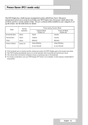
... Power-saving Function Mode Suspend Mode Position A1 Active Power-off Mode Position A2 Inactive Inactive Inactive Blanked Blanked Green Blinking Green Blinking (3 sec Interval) (3 sec Interval) ◆ If the horizontal sync is inactive and the vertical sync active, this PDP Display goes to the screen mute state. ◆ This PDP Display automatically returns to set up this feature. You use a software utility installed on the keyboard. ◆ For energy conservation, turn...
... Power-saving Function Mode Suspend Mode Position A1 Active Power-off Mode Position A2 Inactive Inactive Inactive Blanked Blanked Green Blinking Green Blinking (3 sec Interval) (3 sec Interval) ◆ If the horizontal sync is inactive and the vertical sync active, this PDP Display goes to the screen mute state. ◆ This PDP Display automatically returns to set up this feature. You use a software utility installed on the keyboard. ◆ For energy conservation, turn...
User Manual (ENGLISH)
Page 46
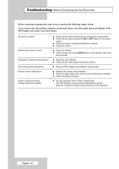
... volume MUTE button on the keyboard. English - 46 Troubleshooting: Before Contacting Service Personnel Before contacting Samsung after-sales service, perform the following simple checks. No sound or picture Normal picture but no sound No picture or black and white picture Sound and picture interference Remote control malfunctions Screen is black and power indicator light blinks steadily. ◆ Check that the mains lead has been connected to a wall socket. ◆ Check that you cannot solve the problem using its power...
... volume MUTE button on the keyboard. English - 46 Troubleshooting: Before Contacting Service Personnel Before contacting Samsung after-sales service, perform the following simple checks. No sound or picture Normal picture but no sound No picture or black and white picture Sound and picture interference Remote control malfunctions Screen is black and power indicator light blinks steadily. ◆ Check that the mains lead has been connected to a wall socket. ◆ Check that you cannot solve the problem using its power...


