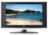
User Manual (ENGLISH)
Page 3
...Level 47 Using the Energy Saving Feature 47 Setting the Function Help 48 Using the V-Chip 48 APPENDIX Identifying Problems 54 Installing the Stand 55 Disconnecting the Stand 55 Installing the Wall Mount Kit (LN-S2641D 56 Installing the Wall Mount Kit (LN-S3241D/LN-S4041D 57 Using the Anti...the Digital-Signal Strength 36 LNA (Low Noise Amplifier 36 PC DISPLAY Using Your TV as a Computer (PC) Display 37 Display Modes 37 Setting up the TV with your PC 38 TIME SETTING Setting the Clock 40 FUNCTION DESCRIPTION Selecting a Menu Language 43 Setting the Blue Screen Mode 43 Selecting the...
...Level 47 Using the Energy Saving Feature 47 Setting the Function Help 48 Using the V-Chip 48 APPENDIX Identifying Problems 54 Installing the Stand 55 Disconnecting the Stand 55 Installing the Wall Mount Kit (LN-S2641D 56 Installing the Wall Mount Kit (LN-S3241D/LN-S4041D 57 Using the Anti...the Digital-Signal Strength 36 LNA (Low Noise Amplifier 36 PC DISPLAY Using Your TV as a Computer (PC) Display 37 Display Modes 37 Setting up the TV with your PC 38 TIME SETTING Setting the Clock 40 FUNCTION DESCRIPTION Selecting a Menu Language 43 Setting the Blue Screen Mode 43 Selecting the...
User Manual (ENGLISH)
Page 4
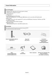
...with no Set-Top Box needed. A special sleep timer. Excellent Picture Quality - Accessories Please make sure the following items are missing, contact your LCD TV. SRS TruSurround XT - Remote Control & Batteries (AAA x 2) (BN59-00511A) Power Cord (3903-000144) Cover-Bottom LN-S2641D/LN-S3241D ...(BN63-02415A) LN-S4041D (BN63-02416A) Stand LN-S2641D (BN96-03192A) LN-S3241D (BN96-03191A) M4 X L16 Screw (6002-001294) Owner's Instructions Warranty Card / Registration Card /Safety Guide ...
...with no Set-Top Box needed. A special sleep timer. Excellent Picture Quality - Accessories Please make sure the following items are missing, contact your LCD TV. SRS TruSurround XT - Remote Control & Batteries (AAA x 2) (BN59-00511A) Power Cord (3903-000144) Cover-Bottom LN-S2641D/LN-S3241D ...(BN63-02415A) LN-S4041D (BN63-02416A) Stand LN-S2641D (BN96-03192A) LN-S3241D (BN96-03191A) M4 X L16 Screw (6002-001294) Owner's Instructions Warranty Card / Registration Card /Safety Guide ...

User Manual (ENGLISH)
Page 5
...Component, PC, HDMI1, and HDMI2 only. POWER INDICATOR Blinks and turns off . Viewing the Control Panel Buttons on the Lower-Right Part of your TV's basic features, including the on-screen menu. The product color and shape may vary depending on the remote control. Press to change channels. In .... In the on-screen menu, use the buttons as you must use the and buttons on and lights up in stand-by mode. SOURCE Toggles between all the available input sources (TV, AV1, AV2, S-Video1, S-Video2, Component, PC, HDMI1, HDMI2). To use the more advanced features, you would use...
...Component, PC, HDMI1, and HDMI2 only. POWER INDICATOR Blinks and turns off . Viewing the Control Panel Buttons on the Lower-Right Part of your TV's basic features, including the on-screen menu. The product color and shape may vary depending on the remote control. Press to change channels. In .... In the on-screen menu, use the buttons as you must use the and buttons on and lights up in stand-by mode. SOURCE Toggles between all the available input sources (TV, AV1, AV2, S-Video1, S-Video2, Component, PC, HDMI1, HDMI2). To use the more advanced features, you would use...
User Manual (ENGLISH)
Page 57
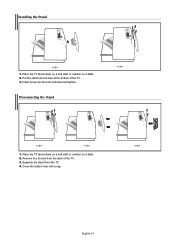
Place the TV faced down on a soft cloth or cushion on a table. 2. Put the stand into the hole indicated and tighten. Disconnecting the Stand < 3 > < 2 > < 3 > 1. Separate the stand from the back of the TV. 3. Cover the bottom hole with a cap. < 4 > English-55 Installing the Stand < 2 > 1. Place the TV faced down on a soft cloth or cushion on a table. 2. Remove four screws from the TV. 4. Insert screw into the hole at the bottom of the TV. 3.
Place the TV faced down on a soft cloth or cushion on a table. 2. Put the stand into the hole indicated and tighten. Disconnecting the Stand < 3 > < 2 > < 3 > 1. Separate the stand from the back of the TV. 3. Cover the bottom hole with a cap. < 4 > English-55 Installing the Stand < 2 > 1. Place the TV faced down on a soft cloth or cushion on a table. 2. Remove four screws from the TV. 4. Insert screw into the hole at the bottom of the TV. 3.

User Manual (ENGLISH)
Page 60
...Diagonal) Power Supply Power Consumption PC Resolution Sound Output Dimensions (WxDxH) Body With stand Weight With stand Environmental Considerations Operating Temperature Operating Humidity Storage Temperature Storage Humidity LN-S2641D 26 inch ... 732.5 mm) 52.25 lbs (23.7 kg) 50 °F to 104 °F (10 °C to 40 °C) 10% to 80%, non-condensing -4 °F to 113 °F (-20 °C to 45 &#...illustration depending on the manufacturer. Fix the Kensington lock to be different depending on the LCD TV (Figure 1), and turn it in the locking direction (Figure 2). 2. Insert the...
...Diagonal) Power Supply Power Consumption PC Resolution Sound Output Dimensions (WxDxH) Body With stand Weight With stand Environmental Considerations Operating Temperature Operating Humidity Storage Temperature Storage Humidity LN-S2641D 26 inch ... 732.5 mm) 52.25 lbs (23.7 kg) 50 °F to 104 °F (10 °C to 40 °C) 10% to 80%, non-condensing -4 °F to 113 °F (-20 °C to 45 &#...illustration depending on the manufacturer. Fix the Kensington lock to be different depending on the LCD TV (Figure 1), and turn it in the locking direction (Figure 2). 2. Insert the...


