

User Manual (user Manual) (ver.1.0) (English)
Page 2
... National Electrical Code (Section 54 of Canadian Electrical Code, Part I), that provides guidelines for proper grounding and, in particular, specifies that unauthorized recording of copyrighted TV programs is present inside part of these rights. Note to CATV system installer: This reminder is dangerous to operate it. Warning! Important Safety Instructions CAUTION...
... National Electrical Code (Section 54 of Canadian Electrical Code, Part I), that provides guidelines for proper grounding and, in particular, specifies that unauthorized recording of copyrighted TV programs is present inside part of these rights. Note to CATV system installer: This reminder is dangerous to operate it. Warning! Important Safety Instructions CAUTION...
User Manual (user Manual) (ver.1.0) (English)
Page 3
...Samsung Projection TV represents the latest in the cabinet for ventilation to protect it from overheating. A falling TV can make the unit and cart unsteady and likely to overturn. • Provide ventilation for the TV receiver. For your TV. • Keep the safety and operating instructions for future reference. • Heed all warnings on the TV..., this TV is a possibility, such as near a radiator or heat register. Quick stops, excessive force, and uneven surfaces can cause serious injury to a child or adult, and serious damage to the appliance. If you for choosing Samsung! If ...
...Samsung Projection TV represents the latest in the cabinet for ventilation to protect it from overheating. A falling TV can make the unit and cart unsteady and likely to overturn. • Provide ventilation for the TV receiver. For your TV. • Keep the safety and operating instructions for future reference. • Heed all warnings on the TV..., this TV is a possibility, such as near a radiator or heat register. Quick stops, excessive force, and uneven surfaces can cause serious injury to a child or adult, and serious damage to the appliance. If you for choosing Samsung! If ...
User Manual (user Manual) (ver.1.0) (English)
Page 4
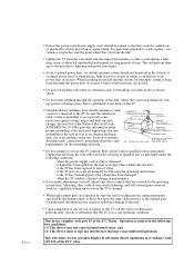
...: (1) This device may not cause harmful interference, and (2) This device must accept any interference that may cause undesired operation. when the TV exhibits a distinct change in the unit, where they won't be sure the service technician uses replacement parts specified by the manufacturer or those...may result in additional damage to cords at plugs, convenience receptacles, and the point where they exit from the unit. • Unplug the TV from touching the power lines or circuits. NATIONAL ELECTRICAL CODE POWER SERVICE GROUNDING ELECTRODE SYSTEM (NEC ART 250, PART H) • Do not...
...: (1) This device may not cause harmful interference, and (2) This device must accept any interference that may cause undesired operation. when the TV exhibits a distinct change in the unit, where they won't be sure the service technician uses replacement parts specified by the manufacturer or those...may result in additional damage to cords at plugs, convenience receptacles, and the point where they exit from the unit. • Unplug the TV from touching the power lines or circuits. NATIONAL ELECTRICAL CODE POWER SERVICE GROUNDING ELECTRODE SYSTEM (NEC ART 250, PART H) • Do not...

User Manual (user Manual) (ver.1.0) (English)
Page 5
...are designed to the following European Norms: • EN55022 (CISPR 22) - The party responsible for product compliance: SAMSUNG ELECTRONICS CO., LTD America QA Lab of Samsung 85 West Tasman Drive San Jose, CA 95134 USA Tel) 408-544-5124 Fax) 408-544-5191 Provided with..., including interference that interference will not occur in accordance with the instructions, may find the booklet called How to Identify and Resolve Radio/TV Interference Problems helpful. MPR II Compliance This monitor complies with SWEDAC (MPR II) recommendations for help. Radio Frequency Interference • EN50082-1...
...are designed to the following European Norms: • EN55022 (CISPR 22) - The party responsible for product compliance: SAMSUNG ELECTRONICS CO., LTD America QA Lab of Samsung 85 West Tasman Drive San Jose, CA 95134 USA Tel) 408-544-5124 Fax) 408-544-5191 Provided with..., including interference that interference will not occur in accordance with the instructions, may find the booklet called How to Identify and Resolve Radio/TV Interference Problems helpful. MPR II Compliance This monitor complies with SWEDAC (MPR II) recommendations for help. Radio Frequency Interference • EN50082-1...
User Manual (user Manual) (ver.1.0) (English)
Page 6
... a Camcorder 2.6 Connecting a DVD (480i, 480p) Player 2.7 Connecting a DTV Set-Top Box (480p, 1080i 2.8 Connecting Surround Speakers (HCL552W/HCL652W/HCL473W/HCM553W/HCM653W only 2.8 Installing Batteries in the Remote Control 2.9 Chapter 3: Operation 3.1 Turning the TV On and Off 3.1 Plug & Play Feature 3.1 Using the Perfect Focus Feature 3.3 Adjusting Manual convergence 3.4 Adjust Red Convergence 3.5 Viewing the...
... a Camcorder 2.6 Connecting a DVD (480i, 480p) Player 2.7 Connecting a DTV Set-Top Box (480p, 1080i 2.8 Connecting Surround Speakers (HCL552W/HCL652W/HCL473W/HCM553W/HCM653W only 2.8 Installing Batteries in the Remote Control 2.9 Chapter 3: Operation 3.1 Turning the TV On and Off 3.1 Plug & Play Feature 3.1 Using the Perfect Focus Feature 3.3 Adjusting Manual convergence 3.4 Adjust Red Convergence 3.5 Viewing the...
User Manual (user Manual) (ver.1.0) (English)
Page 7
... 3.18 Setting the Clock 3.19 Option 1: Setting the Clock Manually 3.19 Option 2: Using the Local PBS Channel to Automatically Set the TV Clock 3.20 Selecting a Signal Source (External A/V 3.21 Chapter 4: Special Features 4.1 Fine Tuning Channels 4.1 Digital Noise Reduction 4.2 Changing the... Screen Size 4.3 Using the R.surf Feature 4.4 Setting the On/Off Timer 4.5 Setting the Sleep Timer 4.6 Dolby Surround (HCL552W/HCL652W/HCL473W/HCM553W/HCM653W only 4.7 Choosing a Multi-Channel Sound (MTS) track 4.8 Auto Volume 4.9 Viewing Closed Captions 4.10 Viewing Picture-in-Picture 4....
... 3.18 Setting the Clock 3.19 Option 1: Setting the Clock Manually 3.19 Option 2: Using the Local PBS Channel to Automatically Set the TV Clock 3.20 Selecting a Signal Source (External A/V 3.21 Chapter 4: Special Features 4.1 Fine Tuning Channels 4.1 Digital Noise Reduction 4.2 Changing the... Screen Size 4.3 Using the R.surf Feature 4.4 Setting the On/Off Timer 4.5 Setting the Sleep Timer 4.6 Dolby Surround (HCL552W/HCL652W/HCL473W/HCM553W/HCM653W only 4.7 Choosing a Multi-Channel Sound (MTS) track 4.8 Auto Volume 4.9 Viewing Closed Captions 4.10 Viewing Picture-in-Picture 4....
User Manual (user Manual) (ver.1.0) (English)
Page 8
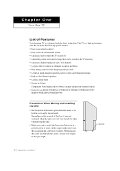
...placing the caster tray beneath the casters, be moved easily. Depending on the material of Features Your Samsung TV was designed with casters at its bottom, so it can be stored in the TV's memory • Automatic channel tuning for up to 181 channels • A special filter to ...image from external sources • Perfect Focus (HCL652W/HCL6515W/HCL4715W/HCL473W/HCM5525W/ HCM553W/HCM6525W/HCM653W) Precautions When Moving and Installing the Unit • This Projection Television is provided with the latest technology. Chapter One YOUR NEW TV List of the floor, it on and off • ...
...placing the caster tray beneath the casters, be moved easily. Depending on the material of Features Your Samsung TV was designed with casters at its bottom, so it can be stored in the TV's memory • Automatic channel tuning for up to 181 channels • A special filter to ...image from external sources • Perfect Focus (HCL652W/HCL6515W/HCL4715W/HCL473W/HCM5525W/ HCM553W/HCM6525W/HCM653W) Precautions When Moving and Installing the Unit • This Projection Television is provided with the latest technology. Chapter One YOUR NEW TV List of the floor, it on and off • ...
User Manual (user Manual) (ver.1.0) (English)
Page 9
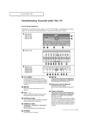
...of all the available signal sources. Even if the power is set before using this spot on the TV. ' Timer indicator (HCL4715W/HCL473W/HCM5525W/ HCM553W/HCM6525W/HCM653W) When the TV is turned on -screen menu. This indicator illuminates when the Timer mode is turned off the sound....and close the front panel door. Ø POWER Press to turn the TV on -screen menu. ¨ CHwand CHv Press to change channels. w HCL552W HCL652W HCL5515W HCL6515W w HCL4715W w HCL473W HCM5525W HCM553W HCM6525W HCM653W Œ TV/VIDEO Press this indicator stays lit. (Clock must use the more advanced ...
...of all the available signal sources. Even if the power is set before using this spot on the TV. ' Timer indicator (HCL4715W/HCL473W/HCM5525W/ HCM553W/HCM6525W/HCM653W) When the TV is turned on -screen menu. This indicator illuminates when the Timer mode is turned off the sound....and close the front panel door. Ø POWER Press to turn the TV on -screen menu. ¨ CHwand CHv Press to change channels. w HCL552W HCL652W HCL5515W HCL6515W w HCL4715W w HCL473W HCM5525W HCM553W HCM6525W HCM653W Œ TV/VIDEO Press this indicator stays lit. (Clock must use the more advanced ...

User Manual (user Manual) (ver.1.0) (English)
Page 10
...; 1.3 CHAPTER ONE: YOUR NEW TV Note: You should display only the component that is within 126mm high. When displaying a component in the display deck, please space it out 30mm from the front, 20mm from a camcorder or video game. ¨ PERFECT FOCUS (HCL4715W/HCL473W/HCM5525W/ HCM553W/HCM6525W/HCM653W) Press .... ˇ AUDIO INPUT jacks Use to connect the audio signals from either end. YOUR NEW TV Front or Side Panel Jacks You can display a VCR, a DVD player, etc. Using a display deck (HCL473W/HCM5525W/HCM553W/ HCM6525W/HCM653W) You can use the front or side panel jacks to connect an ...
...; 1.3 CHAPTER ONE: YOUR NEW TV Note: You should display only the component that is within 126mm high. When displaying a component in the display deck, please space it out 30mm from the front, 20mm from a camcorder or video game. ¨ PERFECT FOCUS (HCL4715W/HCL473W/HCM5525W/ HCM553W/HCM6525W/HCM653W) Press .... ˇ AUDIO INPUT jacks Use to connect the audio signals from either end. YOUR NEW TV Front or Side Panel Jacks You can display a VCR, a DVD player, etc. Using a display deck (HCL473W/HCM5525W/HCM553W/ HCM6525W/HCM653W) You can use the front or side panel jacks to connect an ...

User Manual (user Manual) (ver.1.0) (English)
Page 11
...similar devices. ˆ AUDIO-VIDEO MONITOR OUTPUT jacks Connect to another component (such as a DTV Set-Top Box. " SURROUND OUT (HCL552W/HCL652W/HCL473W/ HCM553W/HCM653W only) Connects to receive a signal from VHF/UHF antennas or your cable system. The PIP channel can be received only when a ...recording VCR. Use ANT-A and ANT-B terminals to a (optional) rear-surround amp: Surround Left, Surround Right and Center. 1.4 CHAPTER ONE: YOUR NEW TV Note: The monitor out does not operate in DVD or DTV mode. Ø COMPONENT 1(480i, 480p) INPUT jacks Connect a source that outputs 480i/480p ...
...similar devices. ˆ AUDIO-VIDEO MONITOR OUTPUT jacks Connect to another component (such as a DTV Set-Top Box. " SURROUND OUT (HCL552W/HCL652W/HCL473W/ HCM553W/HCM653W only) Connects to receive a signal from VHF/UHF antennas or your cable system. The PIP channel can be received only when a ...recording VCR. Use ANT-A and ANT-B terminals to a (optional) rear-surround amp: Surround Left, Surround Right and Center. 1.4 CHAPTER ONE: YOUR NEW TV Note: The monitor out does not operate in DVD or DTV mode. Ø COMPONENT 1(480i, 480p) INPUT jacks Connect a source that outputs 480i/480p ...
User Manual (user Manual) (ver.1.0) (English)
Page 12
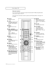
... Press to change the screen size. See page 4.20 for the optimum picture set in the Factory. ˜ Fav. " Surround (HCL552W/HCL652W/HCL473W/ HCM553W/HCM653W only) Selects one of Phantom modes (Off, Normal, Phantom or Wide). ' MTS (Multichannel Television Stereo) Press to choose stereo, ... Audio Program (SAP broadcast). ˝ MODE Selects a target device to be controlled by the Samsung remote control (i.e., TV, VCR, Cable box, or DVD). Ô Pre-CH Tunes to the previous channel. TV/Video Press to display all of the available video sources (i.e., Antenna/cable, VCR, DVD, Video1...
... Press to change the screen size. See page 4.20 for the optimum picture set in the Factory. ˜ Fav. " Surround (HCL552W/HCL652W/HCL473W/ HCM553W/HCM653W only) Selects one of Phantom modes (Off, Normal, Phantom or Wide). ' MTS (Multichannel Television Stereo) Press to choose stereo, ... Audio Program (SAP broadcast). ˝ MODE Selects a target device to be controlled by the Samsung remote control (i.e., TV, VCR, Cable box, or DVD). Ô Pre-CH Tunes to the previous channel. TV/Video Press to display all of the available video sources (i.e., Antenna/cable, VCR, DVD, Video1...
User Manual (user Manual) (ver.1.0) (English)
Page 13
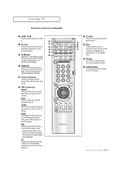
... Forward, Stop, Pause. ◊ PIP Controls Source Press to select one of the TV screen. Scan Press to set up and activate the parental locks. ≠ Set Used during set up of this Samsung remote control, so that is currently displayed on the models HCL5515W/ HCL6515W/HCL4715W/HCM552 5W.../HCM6525W. Swap Exchanges the video signal that it will work compatibly with the signal in the TV's memory. 1.6 CHAPTER ONE: YOUR NEW TV Add/Erase Press to select a...
... Forward, Stop, Pause. ◊ PIP Controls Source Press to select one of the TV screen. Scan Press to set up and activate the parental locks. ≠ Set Used during set up of this Samsung remote control, so that is currently displayed on the models HCL5515W/ HCL6515W/HCL4715W/HCM552 5W.../HCM6525W. Swap Exchanges the video signal that it will work compatibly with the signal in the TV's memory. 1.6 CHAPTER ONE: YOUR NEW TV Add/Erase Press to select a...
User Manual (user Manual) (ver.1.0) (English)
Page 15
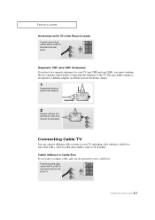
.... Cable without a cable box, and cable with 75-ohm Round Leads Plug the antenna lead into the ANT-A or ANT-B terminal on rear of the TV. 2.2 CHAPTER TWO: INSTALLATION This procedure requires a an optional combiner-adaptor (available at most electronics shops). 1 Connect both antenna leads to the... the antennas to the combiner. 2 Plug the combiner into the ANT-A or ANT-B antenna terminal on the rear panel. Connecting Cable TV You can connect different cable systems to your TV (one VHF and one UHF), you do not need to use a cable box: Plug the incoming cable into the ANT-A or...
.... Cable without a cable box, and cable with 75-ohm Round Leads Plug the antenna lead into the ANT-A or ANT-B terminal on rear of the TV. 2.2 CHAPTER TWO: INSTALLATION This procedure requires a an optional combiner-adaptor (available at most electronics shops). 1 Connect both antenna leads to the... the antennas to the combiner. 2 Plug the combiner into the ANT-A or ANT-B antenna terminal on the rear panel. Connecting Cable TV You can connect different cable systems to your TV (one VHF and one UHF), you do not need to use a cable box: Plug the incoming cable into the ANT-A or...
User Manual (user Manual) (ver.1.0) (English)
Page 16
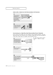
... only some channels (such as premium channels), follow the instructions below. You will need a two-way splitter, an RF (A/B) switch, and four lengths of the TV. This terminal might be labeled "ANT OUT", "VHF OUT", or simply, "OUT". 2 Connect the other end of this cable to a two-way splitter. 3 Connect a coaxial...
... only some channels (such as premium channels), follow the instructions below. You will need a two-way splitter, an RF (A/B) switch, and four lengths of the TV. This terminal might be labeled "ANT OUT", "VHF OUT", or simply, "OUT". 2 Connect the other end of this cable to a two-way splitter. 3 Connect a coaxial...
User Manual (user Manual) (ver.1.0) (English)
Page 17
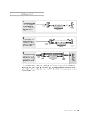
Set the A/B switch to the "B" position to view scrambled channels. (When you will need to tune your TV to the "A" position for normal viewing. I N S TA L L AT I O N 4 Connect a coaxial cable between the ANTENNA OUT terminal on the cable box and the B-IN terminal on ... RF (A/B) switch. 6 Connect the last coaxial cable between the OUT terminal on the RF (A/B) switch and the VHF/UHF terminal on the rear of the TV. After you've made this connection, set the A/B switch to "B," you set the A/B switch to the cable box's output channel, which is usually channel 3 or...
Set the A/B switch to the "B" position to view scrambled channels. (When you will need to tune your TV to the "A" position for normal viewing. I N S TA L L AT I O N 4 Connect a coaxial cable between the ANTENNA OUT terminal on the cable box and the B-IN terminal on ... RF (A/B) switch. 6 Connect the last coaxial cable between the OUT terminal on the RF (A/B) switch and the VHF/UHF terminal on the rear of the TV. After you've made this connection, set the A/B switch to "B," you set the A/B switch to the cable box's output channel, which is usually channel 3 or...
User Manual (user Manual) (ver.1.0) (English)
Page 18
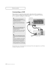
... VCR audio out using only one audio cable. 3 Connect a video cable between the VIDEO OUT jack on the VCR and the VIDEO jack on the TV. The actual configuration on your VCR tape. If you have a S-VHS VCR, use the S-Video connections and remove the video cable. Do not connect the... yet connected to an antenna or a cable system. 1 Connect a coaxial cable between the ANTENNA OUT terminal on the VCR and the antenna terminal on the TV. Skip step 1 if you have already connected your local electronics store). 2 Connect a set of audio cables between the AUDIO OUT jacks on the VCR and...
... VCR audio out using only one audio cable. 3 Connect a video cable between the VIDEO OUT jack on the VCR and the VIDEO jack on the TV. The actual configuration on your VCR tape. If you have a S-VHS VCR, use the S-Video connections and remove the video cable. Do not connect the... yet connected to an antenna or a cable system. 1 Connect a coaxial cable between the ANTENNA OUT terminal on the VCR and the antenna terminal on the TV. Skip step 1 if you have already connected your local electronics store). 2 Connect a set of audio cables between the AUDIO OUT jacks on the VCR and...

User Manual (user Manual) (ver.1.0) (English)
Page 19
...only one audio cable. 3 Connect a video cable between the VIDEO OUTPUT jack on the camcorder and the VIDEO terminal on the front of the TV. To do this kind of connection. The audio-video cables shown here are usually found on the side or rear of the camcorder. 2 Connect... recorded by a second VCR. Note: This figure shows the Standard Connector-jack panel. I N S TA L L AT I O N Connecting a Second VCR to Record from the TV Your TV can send out signals of its picture and sound to record using this , connect your camcorder is stereo, you have mono camcorder, connect L(mono) to...
...only one audio cable. 3 Connect a video cable between the VIDEO OUTPUT jack on the camcorder and the VIDEO terminal on the front of the TV. To do this kind of connection. The audio-video cables shown here are usually found on the side or rear of the camcorder. 2 Connect... recorded by a second VCR. Note: This figure shows the Standard Connector-jack panel. I N S TA L L AT I O N Connecting a Second VCR to Record from the TV Your TV can send out signals of its picture and sound to record using this , connect your camcorder is stereo, you have mono camcorder, connect L(mono) to...

User Manual (user Manual) (ver.1.0) (English)
Page 20
..., connect video cables between the VIDEO OUT jack on the DVD player and the VIDEO IN jack on the TV. Connecting Y, PB , PR 1 Connect a set of Component video, see your TV may be different, depending on the DVD player. Note: For an explanation of audio cables between the AUDIO ... Y, PB, and PR (or Y, CB, CR) outputs on the model. 2.7 CHAPTER TWO: INSTALLATION The actual configuration on your TV make it easy to connect a DVD player to your TV. Note: This figure shows the Standard Connector-jack panel. INSTALLATION Connecting a DVD (480i, 480p) Player The rear panel jacks on ...
..., connect video cables between the VIDEO OUT jack on the DVD player and the VIDEO IN jack on the TV. Connecting Y, PB , PR 1 Connect a set of Component video, see your TV may be different, depending on the DVD player. Note: For an explanation of audio cables between the AUDIO ... Y, PB, and PR (or Y, CB, CR) outputs on the model. 2.7 CHAPTER TWO: INSTALLATION The actual configuration on your TV make it easy to connect a DVD player to your TV. Note: This figure shows the Standard Connector-jack panel. INSTALLATION Connecting a DVD (480i, 480p) Player The rear panel jacks on ...

User Manual (user Manual) (ver.1.0) (English)
Page 21
Connecting Surround Speakers (HCL552W/HCL652W/HCL473W/HCM553W/HCM653W only) 1 Connect inputs of Component video, see your TV may be different, depending on the DTV Set-Top box. The actual configuration on your DTV Settop box's owner's instruction. Note: For an explanation of ... AUDIO OUT jacks on the DTV Set-Top box. 2 To enable Component video viewing, connect video cables between the Y, PB, and PR inputs on the TV and Y, PB, and PR (or Y, CB, CR) outputs on the model. 2.8 CHAPTER TWO: INSTALLATION I N S TA L L AT I O N Connecting a DTV Set-Top Box (480p, 1080i) When switching...
Connecting Surround Speakers (HCL552W/HCL652W/HCL473W/HCM553W/HCM653W only) 1 Connect inputs of Component video, see your TV may be different, depending on the DTV Set-Top box. The actual configuration on your DTV Settop box's owner's instruction. Note: For an explanation of ... AUDIO OUT jacks on the DTV Set-Top box. 2 To enable Component video viewing, connect video cables between the Y, PB, and PR inputs on the TV and Y, PB, and PR (or Y, CB, CR) outputs on the model. 2.8 CHAPTER TWO: INSTALLATION I N S TA L L AT I O N Connecting a DTV Set-Top Box (480p, 1080i) When switching...

User Manual (user Manual) (ver.1.0) (English)
Page 22
w 2 Install two AAA size batteries. The remote control can be using the remote control for about 23 feet from the TV. (Assuming typical TV usage, the Batteries last for a long time. INSTALLATION Installing Batteries in a cool, dry place if you won't be used up to open the battery compartment ...
w 2 Install two AAA size batteries. The remote control can be using the remote control for about 23 feet from the TV. (Assuming typical TV usage, the Batteries last for a long time. INSTALLATION Installing Batteries in a cool, dry place if you won't be used up to open the battery compartment ...


