
User Manual
Page 5
Put your monitor in a location with low humidity and a minimum of dust. Place the monitor on the monitor cabinet. Do not drop the monitor when moving it. Do not place the monitor face down the monitor carefully. z The monitor can cause injury by falling. z The TFT-LCD surface may be damaged or broken. Installation Do not cover the vents on a flat and stable surface. z An electric shock or fire could be damaged. z This may cause a breakdown or fire. Set down . z Bad ventilation may cause damage to the product or human body. z It could result inside the monitor.
Put your monitor in a location with low humidity and a minimum of dust. Place the monitor on the monitor cabinet. Do not drop the monitor when moving it. Do not place the monitor face down the monitor carefully. z The monitor can cause injury by falling. z The TFT-LCD surface may be damaged or broken. Installation Do not cover the vents on a flat and stable surface. z An electric shock or fire could be damaged. z This may cause a breakdown or fire. Set down . z Bad ventilation may cause damage to the product or human body. z It could result inside the monitor.
User Manual
Page 6
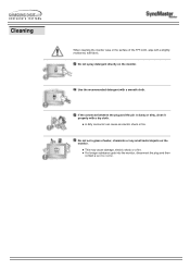
... dusty or dirty, clean it properly with a smooth cloth. z A dirty connector can cause an electric shock or fire. z If a foreign substance gets into the monitor, disconnect the plug and then contact a service center. Do not set a glass of the TFT-LCD, wipe with a slightly moistened, soft fabric. z This may... cause damage, electric shock or a fire. Cleaning When cleaning the monitor case or the surface of water, chemicals or any small metal objects on the monitor. Do not spray detergent directly on the...
... dusty or dirty, clean it properly with a smooth cloth. z A dirty connector can cause an electric shock or fire. z If a foreign substance gets into the monitor, disconnect the plug and then contact a service center. Do not set a glass of the TFT-LCD, wipe with a slightly moistened, soft fabric. z This may... cause damage, electric shock or a fire. Cleaning When cleaning the monitor case or the surface of water, chemicals or any small metal objects on the monitor. Do not spray detergent directly on the...

User Manual
Page 7
...rest for 5 minutes. z This may cause an electric shock or fire. z This will reduce eye fatigue. Never insert anything metallic into the monitor openings. No user serviceable parts inside. Do not try to be away from it immediately and contact an authorized dealer or service. Do not move ... may cause an electric shock or a fire. z Change the mode to energy save or set a screensaver to moving picture when you should let your monitor does not operate normally - Other Do not remove cover(or back). unplug it - z This may cause an electric shock, fire or injury. If ...
...rest for 5 minutes. z This may cause an electric shock or fire. z This will reduce eye fatigue. Never insert anything metallic into the monitor openings. No user serviceable parts inside. Do not try to be away from it immediately and contact an authorized dealer or service. Do not move ... may cause an electric shock or a fire. z Change the mode to energy save or set a screensaver to moving picture when you should let your monitor does not operate normally - Other Do not remove cover(or back). unplug it - z This may cause an electric shock, fire or injury. If ...

User Manual
Page 8
Power Cord Cover-hole Remote Control / Batteries (AAA X 2) Monitor Signal Cable (15 pin D-Sub) BNC to RCA Adaptorjack RS232C CABLE User's Guide CD Sold separately Warranty Card (Not available in all locations) Temporary Stand Wall Mount KIT Speaker Set Stand Kit PIVOT Installation CD Contact a local Samsung Electronics service center to buy optional items. Unpacking Please make sure the following items are missing, contact your monitor. If any items are included with your dealer.
Power Cord Cover-hole Remote Control / Batteries (AAA X 2) Monitor Signal Cable (15 pin D-Sub) BNC to RCA Adaptorjack RS232C CABLE User's Guide CD Sold separately Warranty Card (Not available in all locations) Temporary Stand Wall Mount KIT Speaker Set Stand Kit PIVOT Installation CD Contact a local Samsung Electronics service center to buy optional items. Unpacking Please make sure the following items are missing, contact your monitor. If any items are included with your dealer.

User Manual
Page 9
Auto button 2. Menu button 7. Exit button 4. Front For detailed information concerning the monitor functions, refer to User Controls under Adjusting Your Monitor. Navigate button (Up-Down Button) 5. Power button 8. Adjust button (Left-Right Button) / Volume button 6. Source button 3. The monitor's front configuration may vary slightly depending on the monitor model. 1. Remote Control Sensor Power indicator 9.
Auto button 2. Menu button 7. Exit button 4. Front For detailed information concerning the monitor functions, refer to User Controls under Adjusting Your Monitor. Navigate button (Up-Down Button) 5. Power button 8. Adjust button (Left-Right Button) / Volume button 6. Source button 3. The monitor's front configuration may vary slightly depending on the monitor model. 1. Remote Control Sensor Power indicator 9.

User Manual
Page 10
The monitor's rear configuration may vary slightly depending on the monitor model. 1. PC Video Connection Terminal : Using DVI Cable (DVI-D to Connecting Cables under Setup. Rear SyncMaster 403T For detailed information concerning cable connections, refer to DVI-D) - Power On/Off Switch 2. RGB 1 mode (Analog PC) 5. PC Video Connection Terminal : Using D-Sub Cable (15 pin D-Sub) - EXTERNAL CONTROL (RS232C Serial PORT) : MDC(Multiple Device Control) Program Port 4. Power port 3. RGB 2 mode (Digital PC)
The monitor's rear configuration may vary slightly depending on the monitor model. 1. PC Video Connection Terminal : Using DVI Cable (DVI-D to Connecting Cables under Setup. Rear SyncMaster 403T For detailed information concerning cable connections, refer to DVI-D) - Power On/Off Switch 2. RGB 1 mode (Analog PC) 5. PC Video Connection Terminal : Using D-Sub Cable (15 pin D-Sub) - EXTERNAL CONTROL (RS232C Serial PORT) : MDC(Multiple Device Control) Program Port 4. Power port 3. RGB 2 mode (Digital PC)

User Manual
Page 11
... : Video 2 mode (Input) 11. Component Audio Connection Terminal (Input) : When the input signal is connected to Terminal 8 or 10, the audio must be connect to 5 monitors supported. 14. Loopout Connection : Up to this terminal only. 13. Component Connection : connecting Pb, Y, Pr port 7. Speaker Out 15. Kensington Lock PC Video Loopout Connection...
... : Video 2 mode (Input) 11. Component Audio Connection Terminal (Input) : When the input signal is connected to Terminal 8 or 10, the audio must be connect to 5 monitors supported. 14. Loopout Connection : Up to this terminal only. 13. Component Connection : connecting Pb, Y, Pr port 7. Speaker Out 15. Kensington Lock PC Video Loopout Connection...

User Manual
Page 12
Rear SyncMaster 323T For detailed information concerning cable connections, refer to DVI-D) - RGB 1 mode (Analog PC) 5. PC Video Connection Terminal : Using DVI Cable (DVI-D to Connecting Cables under Setup. EXTERNAL CONTROL (RS232C Serial PORT) : MDC(Multiple Device Control) Program Port 4. PC Video Connection Terminal : Using D-Sub Cable (15 pin D-Sub) - The monitor's rear configuration may vary slightly depending on the monitor model. 1. Power port 3. Power On/Off Switch 2. RGB 2 mode (Digital PC)
Rear SyncMaster 323T For detailed information concerning cable connections, refer to DVI-D) - RGB 1 mode (Analog PC) 5. PC Video Connection Terminal : Using DVI Cable (DVI-D to Connecting Cables under Setup. EXTERNAL CONTROL (RS232C Serial PORT) : MDC(Multiple Device Control) Program Port 4. PC Video Connection Terminal : Using D-Sub Cable (15 pin D-Sub) - The monitor's rear configuration may vary slightly depending on the monitor model. 1. Power port 3. Power On/Off Switch 2. RGB 2 mode (Digital PC)

User Manual
Page 13
... Connection Terminal : Video 1 mode (Input) 9. CVBS, S-Video Audio Connection Terminal (Input) : When the input signal is connected to Terminal 6, the audio must be connect to 5 monitors supported. 14.
... Connection Terminal : Video 1 mode (Input) 9. CVBS, S-Video Audio Connection Terminal (Input) : When the input signal is connected to Terminal 6, the audio must be connect to 5 monitors supported. 14.

User Manual
Page 14
... 0.23 to 33 feet (7cm to 10m) and 30 degrees to the left and right of the Remote Control Unit functions, refer to Adjusting Your Monitor > User Controls > User Control Buttons > Remote Control buttons. Power button 2. Mute button 4. Number buttons 7. P.Size button 10. Display button 12. ...button 2. Exit button 15. Auto button 3. Source button 6. Slide in the cover. The Remote control may vary slightly depending on the monitor model. PIP Size button 9. Sleep button 13. Slide out the cover pressing part marked . 2. Remote Control For detailed information of the...
... 0.23 to 33 feet (7cm to 10m) and 30 degrees to the left and right of the Remote Control Unit functions, refer to Adjusting Your Monitor > User Controls > User Control Buttons > Remote Control buttons. Power button 2. Mute button 4. Number buttons 7. P.Size button 10. Display button 12. ...button 2. Exit button 15. Auto button 3. Source button 6. Slide in the cover. The Remote control may vary slightly depending on the monitor model. PIP Size button 9. Sleep button 13. Slide out the cover pressing part marked . 2. Remote Control For detailed information of the...

User Manual
Page 15
Mechanical Lay-out SyncMaster 403T 2. Monitor Head Mechanical Lay-out 1.
Mechanical Lay-out SyncMaster 403T 2. Monitor Head Mechanical Lay-out 1.

User Manual
Page 18
Mechanical Lay-out SyncMaster 323T 2. Monitor Head Mechanical Lay-out 1.
Mechanical Lay-out SyncMaster 323T 2. Monitor Head Mechanical Lay-out 1.

User Manual
Page 21
... Kit Only the supplied bolts should be responsible for any problems caused by using the 'Cover-Hole' when attaching the wall mount kit. 2. Samsung Electronics will not be used to remove the 'Cover-Protector' when attaching the provided Semi Stand or stand kit (sold separately) is provided only... for use the Semi Stand as a regular stand and Samsung Electronics is not responsible for damages caused by using it instead of the monitor, where the stand is not intended for screen adjustment before the stand kit or wall mount kit (sold...
... Kit Only the supplied bolts should be responsible for any problems caused by using the 'Cover-Hole' when attaching the wall mount kit. 2. Samsung Electronics will not be used to remove the 'Cover-Protector' when attaching the provided Semi Stand or stand kit (sold separately) is provided only... for use the Semi Stand as a regular stand and Samsung Electronics is not responsible for damages caused by using it instead of the monitor, where the stand is not intended for screen adjustment before the stand kit or wall mount kit (sold...

User Manual
Page 22
Put the stand into the hole indicated and tighten. (M4 x 15) Make sure you put the parts in the right direction and in the right place. (M4 x 15) 3. Be sure to protect the hole at the bottom of the monitor, where the stand is inserted. Installing Stand Kit 2. Insert screw into the hole at the bottom of the monitor. 4. A 'Cover-Protector' is used to remove the 'Cover-Protector' when attaching the provided Semi Stand or stand kit (sold separately) 1. Installing Stand Kit (sold separately) and cover the hole using the 'Cover-Hole' when attaching the wall mount kit. 2.
Put the stand into the hole indicated and tighten. (M4 x 15) Make sure you put the parts in the right direction and in the right place. (M4 x 15) 3. Be sure to protect the hole at the bottom of the monitor, where the stand is inserted. Installing Stand Kit 2. Insert screw into the hole at the bottom of the monitor. 4. A 'Cover-Protector' is used to remove the 'Cover-Protector' when attaching the provided Semi Stand or stand kit (sold separately) 1. Installing Stand Kit (sold separately) and cover the hole using the 'Cover-Hole' when attaching the wall mount kit. 2.

User Manual
Page 23
... 1. A 'Cover-Protector' is not intended for use the Semi Stand as a regular stand and Samsung Electronics is inserted. Be sure to protect the hole at the bottom of the monitor. The Semi Stand is used . Samsung Electronics will not be used to remove the 'Cover-Protector' when attaching the provided Semi Stand.... Set up the left and right stands respectively. 3. Never use as the regular stand. Insert screw into the hole at the bottom of the monitor, where the stand is not responsible for any problems caused by using the 'Cover-Hole' when attaching the wall mount kit. 2.
... 1. A 'Cover-Protector' is not intended for use the Semi Stand as a regular stand and Samsung Electronics is inserted. Be sure to protect the hole at the bottom of the monitor. The Semi Stand is used . Samsung Electronics will not be used to remove the 'Cover-Protector' when attaching the provided Semi Stand.... Set up the left and right stands respectively. 3. Never use as the regular stand. Insert screw into the hole at the bottom of the monitor, where the stand is not responsible for any problems caused by using the 'Cover-Hole' when attaching the wall mount kit. 2.

User Manual
Page 24
...) and cover the hole using the 'Cover-Hole' when attaching the wall mount kit. 2. Be sure to protect the hole at the bottom of the monitor, where the stand is used to remove the 'Cover-Protector' when attaching the provided Semi Stand or stand kit (sold separately) 1. Put the stand into...
...) and cover the hole using the 'Cover-Hole' when attaching the wall mount kit. 2. Be sure to protect the hole at the bottom of the monitor, where the stand is used to remove the 'Cover-Protector' when attaching the provided Semi Stand or stand kit (sold separately) 1. Put the stand into...

User Manual
Page 25
... like DVDs, VCRs or Camcorders as well as your computer may be connected to a Computer 1. For detailed information on power switch. 2. Connecting to the monitor. Trun on connecting AV input devices, refer to the 15 pin D-sub Port on the video card. There are 3 ways to connect the signal cable... to buy optional items. Connect the signal cable to User Controls under Adjusting Your Monitor. Using the BNC (Analog) connector on the back of the followings : 2-1. Contact a local Samsung Electronics service center to your...
... like DVDs, VCRs or Camcorders as well as your computer may be connected to a Computer 1. For detailed information on power switch. 2. Connecting to the monitor. Trun on connecting AV input devices, refer to the 15 pin D-sub Port on the video card. There are 3 ways to connect the signal cable... to buy optional items. Connect the signal cable to User Controls under Adjusting Your Monitor. Using the BNC (Analog) connector on the back of the followings : 2-1. Contact a local Samsung Electronics service center to your...

User Manual
Page 26
... the DVD player. 2. Connect a set of the monitor using audio cables. 3. BNC cable is optional. 2. Connecting Your Monitor 2. Connect a BNC cable between the Component Audio Connection Terminal on the Monitor and the AUDIO OUT jacks on the monitor's front or remote control. 4. Select BNC that is... to a DVD Player 1. Then, start the VCR or Camcorders with a DVD disc inserted. Pb, Y, Pr port on the Monitor and the Pb Y, Pr jacks on the monitor's front or remote control. 4. Select Video 1 or Video 2 that is connected to the S-Video Connection Terminal or CVBS Video ...
... the DVD player. 2. Connect a set of the monitor using audio cables. 3. BNC cable is optional. 2. Connecting Your Monitor 2. Connect a BNC cable between the Component Audio Connection Terminal on the Monitor and the AUDIO OUT jacks on the monitor's front or remote control. 4. Select BNC that is... to a DVD Player 1. Then, start the VCR or Camcorders with a DVD disc inserted. Pb, Y, Pr port on the Monitor and the Pb Y, Pr jacks on the monitor's front or remote control. 4. Select Video 1 or Video 2 that is connected to the S-Video Connection Terminal or CVBS Video ...

User Manual
Page 27
... on the side or back of audio cables between the AUDIO OUTPUT jacks on the camcorder and the CVBS, S-Video Audio Connection Terminal on the Monitor. 2. For an explanation of Component video, see your camcorder is stereo, you need to connect a set of the camcorder. Connect a video cable ...Set Top Box. 2. Connect a set of audio cables between the Component Audio Connection Terminal on the Monitor and the AUDIO OUT jacks on the monitor's front or remote control. Pb, Y, Pr port on the Monitor and the Pb, Y, Pr jacks on the camcorder. Connect a BNC cable between the VIDEO OUTPUT ...
... on the side or back of audio cables between the AUDIO OUTPUT jacks on the camcorder and the CVBS, S-Video Audio Connection Terminal on the Monitor. 2. For an explanation of Component video, see your camcorder is stereo, you need to connect a set of the camcorder. Connect a video cable ...Set Top Box. 2. Connect a set of audio cables between the Component Audio Connection Terminal on the Monitor and the AUDIO OUT jacks on the monitor's front or remote control. Pb, Y, Pr port on the Monitor and the Pb, Y, Pr jacks on the camcorder. Connect a BNC cable between the VIDEO OUTPUT ...

User Manual
Page 28
Connecting Speakers 1. Connect the speaker connection cable between the speaker connection jack on the rear of the SET and the speaker connection jack on the rear of audio cables between the AUX L, R jacks on the AUDIO SYSTEM and the Audio Line-out Connection Terminal on the Monitor. Connecting Your Monitor 6. Connect a set of the speaker. Do not move the SET holding the speaker when the SET is connected to an Audio System 1. Connecting to the speaker. The speaker-bracket for connecting the SET speaker may be damaged. 7. Tighten the SET and the speaker using the screws. 2.
Connecting Speakers 1. Connect the speaker connection cable between the speaker connection jack on the rear of the SET and the speaker connection jack on the rear of audio cables between the AUX L, R jacks on the AUDIO SYSTEM and the Audio Line-out Connection Terminal on the Monitor. Connecting Your Monitor 6. Connect a set of the speaker. Do not move the SET holding the speaker when the SET is connected to an Audio System 1. Connecting to the speaker. The speaker-bracket for connecting the SET speaker may be damaged. 7. Tighten the SET and the speaker using the screws. 2.


