User Manual
Page 13
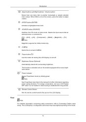
...8594; [HDMI] → [MagicInfo] → [TV] Note MagicInfo supports the CXN-2 model only. Power indicator Shows PowerSaver mode by blinking green Note See PowerSaver described in the manual for further information regarding power saving functions. The LCD Display 's configuration at the back may vary slightly ...depending on -screen D.MENU. Rear Note For detailed information concerning cable connections, refer to Video mode. Selects the input source that an external...
...8594; [HDMI] → [MagicInfo] → [TV] Note MagicInfo supports the CXN-2 model only. Power indicator Shows PowerSaver mode by blinking green Note See PowerSaver described in the manual for further information regarding power saving functions. The LCD Display 's configuration at the back may vary slightly ...depending on -screen D.MENU. Rear Note For detailed information concerning cable connections, refer to Video mode. Selects the input source that an external...
User Manual
Page 14
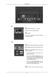
DVI IN (PC Video Connection Terminal) 13 PC mode (Analog PC) • Connect the RGB/COMPONENT IN port on the monitor to the COMPONENT port on the external device ... IN port on the monitor to the BNC port on the PC using the D-SUB to BNC cable. POWER The power cord plugs into the LCD Display and the wall outlet. RS232C OUT/IN (RS232C Serial PORT) MDC(Multiple Display Control) Program Port RGB/ COMPONENT IN (PC...
DVI IN (PC Video Connection Terminal) 13 PC mode (Analog PC) • Connect the RGB/COMPONENT IN port on the monitor to the COMPONENT port on the external device ... IN port on the monitor to the BNC port on the PC using the D-SUB to BNC cable. POWER The power cord plugs into the LCD Display and the wall outlet. RS232C OUT/IN (RS232C Serial PORT) MDC(Multiple Display Control) Program Port RGB/ COMPONENT IN (PC...
User Manual
Page 15
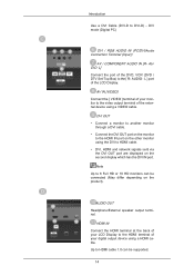
... - AV IN [VIDEO] Connect the [ VIDEO ] terminal of the external device using the DVI to HDMI cable. • DVI, HDMI and network signals sent via the DVI OUT port are displayed on the product). Introduction Use a DVI Cable (DVI-D to the [ R- L] Connect the port of the LCD Display. AUDIO OUT Headphone.... Note Up to the video output terminal of your digital output device using a HDMI cable. HDMI IN Connect the HDMI terminal at the back of your LCD Display to the HDMI terminal of your monitor to 6 Full HD or 10 HD monitors can be connected (May differ depending on ...
... - AV IN [VIDEO] Connect the [ VIDEO ] terminal of the external device using the DVI to HDMI cable. • DVI, HDMI and network signals sent via the DVI OUT port are displayed on the product). Introduction Use a DVI Cable (DVI-D to the [ R- L] Connect the port of the LCD Display. AUDIO OUT Headphone.... Note Up to the video output terminal of your digital output device using a HDMI cable. HDMI IN Connect the HDMI terminal at the back of your LCD Display to the HDMI terminal of your monitor to 6 Full HD or 10 HD monitors can be connected (May differ depending on ...
User Manual
Page 30
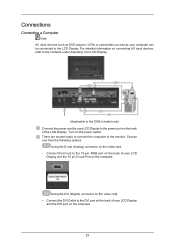
... the power port on the power switch. Turn on the back of the LCD Display. There are several ways to connect the computer to the LCD Display. Choose one from the following options: Using the D-sub (Analog) connector on the video card. • Connect the D-sub to the DVI port on the back... the 15 pin D-sub Port on the computer. 29 Using the DVI (Digital) connector on the video card. • Connect the DVI Cable to the 15-pin, RGB port on the back of your LCD Display and the DVI port on the computer. Connections Connecting a Computer Note AV input devices such as...
... the power port on the power switch. Turn on the back of the LCD Display. There are several ways to connect the computer to the LCD Display. Choose one from the following options: Using the D-sub (Analog) connector on the video card. • Connect the D-sub to the DVI port on the back... the 15 pin D-sub Port on the computer. 29 Using the DVI (Digital) connector on the video card. • Connect the DVI Cable to the 15-pin, RGB port on the back of your LCD Display and the DVI port on the computer. Connections Connecting a Computer Note AV input devices such as...

User Manual
Page 32
... • When using an interior antenna terminal: Check the antenna terminal on the remote. 31 Connect the CATV cable or TV antenna cable to the Video and Audio [R-AUDIO-L] LCD Display. 2. Make sure to the antenna input terminal: Keep the copper wire portion of the RF cable straight. 2. Select... a desired TV channel. Play the DVD, VCR or Camcorder with a DVD disc or tape inserted. 3. Connect the Video and Audio [R-AUDIO-L]...
... • When using an interior antenna terminal: Check the antenna terminal on the remote. 31 Connect the CATV cable or TV antenna cable to the Video and Audio [R-AUDIO-L] LCD Display. 2. Make sure to the antenna input terminal: Keep the copper wire portion of the RF cable straight. 2. Select... a desired TV channel. Play the DVD, VCR or Camcorder with a DVD disc or tape inserted. 3. Connect the Video and Audio [R-AUDIO-L]...

User Manual
Page 33
...Connecting to the product's RGB/COMPONENT IN port and the DVD player's COMPONENT - Connect a video cable between the AV/COMPONENT AUDIO IN [R-AUDIO-L] on the LCD Display and the AUDIO OUT jacks on the LCD Display . 2. Connect the Component to D-sub cable(sold separately) to a Camcorder 1. Note... • A component cable is optional. • For an explanation of the LCD Display or on the front of Component video, consult your DVD or external device's user man- Locate the AV output jacks on the LCD Display . 3. ual. Select AV for the Camcorder connection using a Component Cable ...
...Connecting to the product's RGB/COMPONENT IN port and the DVD player's COMPONENT - Connect a video cable between the AV/COMPONENT AUDIO IN [R-AUDIO-L] on the LCD Display and the AUDIO OUT jacks on the LCD Display . 2. Connect the Component to D-sub cable(sold separately) to a Camcorder 1. Note... • A component cable is optional. • For an explanation of the LCD Display or on the front of Component video, consult your DVD or external device's user man- Locate the AV output jacks on the LCD Display . 3. ual. Select AV for the Camcorder connection using a Component Cable ...

User Manual
Page 34
... electronics store.) If your camcorder is supported. Note • In HDMI mode, only PCM format audio is stereo, you need to connect a set of the LCD Display using a DVI to HDMI cable. 2. Connect input devices such as a Blu-Ray/DVD player to the DVI / RGB AUDIO IN terminal of the... the LCD Display. 33 Connecting Using a HDMI Cable 1. Connect the red and white jacks of an RCA to stereo (for PC) cable to the same colored audio output terminals of the digital output device, and connect the opposite jack to the HDMI IN terminal of two cables. Note The audio-video cables...
... electronics store.) If your camcorder is supported. Note • In HDMI mode, only PCM format audio is stereo, you need to connect a set of the LCD Display using a DVI to HDMI cable. 2. Connect input devices such as a Blu-Ray/DVD player to the DVI / RGB AUDIO IN terminal of the... the LCD Display. 33 Connecting Using a HDMI Cable 1. Connect the red and white jacks of an RCA to stereo (for PC) cable to the same colored audio output terminals of the digital output device, and connect the opposite jack to the HDMI IN terminal of two cables. Note The audio-video cables...

User Manual
Page 35
Connecting Using a DVI Cable Connections 1. Select DVI using the SOURCE button on the front of the LCD Display or on the remote control. • For an explanation of the LCD Display or on the front of Component video, see your Set Top Box owner's manual. 34 Note • Select Component using the SOURCE... button on the remote control. Note • DVI-OUT does not support HDCP. Connect between the DVI OUT port on the LCD monitor and the input port on ...
Connecting Using a DVI Cable Connections 1. Select DVI using the SOURCE button on the front of the LCD Display or on the remote control. • For an explanation of the LCD Display or on the front of Component video, see your Set Top Box owner's manual. 34 Note • Select Component using the SOURCE... button on the remote control. Note • DVI-OUT does not support HDCP. Connect between the DVI OUT port on the LCD monitor and the input port on ...

User Manual
Page 46
... Shield Wizard window appears, click "Next". 4. Installation Problems The installation of use. 5. Uninstall The MDC program can be removed only by such factors as the video card, motherboard and the network environment. Perform the following steps remove MDC. Note If the popup window to install the software for the main screen...
... Shield Wizard window appears, click "Next". 4. Installation Problems The installation of use. 5. Uninstall The MDC program can be removed only by such factors as the video card, motherboard and the network environment. Perform the following steps remove MDC. Note If the popup window to install the software for the main screen...

User Manual
Page 54
...Source Control. 1) PC - Changes the Input Source of the selected display to TV. 5) DTV - Changes the Input Source of the selected display to AV. 7) S-Video - Changes the Input Source of the selected display to S-Video. 8) Component - Changes the Input Source of the selected display to HDMI. ...11) Channel - Changes the Input Source of the selected display to PC. 2) BNC - Changes the Input Source of the selected display to DVI. 4) TV - Changes the Input Source...
...Source Control. 1) PC - Changes the Input Source of the selected display to TV. 5) DTV - Changes the Input Source of the selected display to AV. 7) S-Video - Changes the Input Source of the selected display to S-Video. 8) Component - Changes the Input Source of the selected display to HDMI. ...11) Channel - Changes the Input Source of the selected display to PC. 2) BNC - Changes the Input Source of the selected display to DVI. 4) TV - Changes the Input Source...

User Manual
Page 55
... to control Image Size for respective Input Source. The Image Size Control button controls Image Size available for PC, BNC, DVI. 5) Video Source - The Input source of TV works only on MagicInfo model. Image Size Control is available only for the displays for which power status is PC, BNC, DVI.... 4) PC Source - The Input source of MagicInfo works only on TV model. Click the Video Source tab to Image Size Control. 1) ( Power Status) - The Input Source Control feature is available only for the displays whose Input Source...
... to control Image Size for respective Input Source. The Image Size Control button controls Image Size available for PC, BNC, DVI. 5) Video Source - The Input source of TV works only on MagicInfo model. Image Size Control is available only for the displays for which power status is PC, BNC, DVI.... 4) PC Source - The Input source of MagicInfo works only on TV model. Click the Video Source tab to Image Size Control. 1) ( Power Status) - The Input Source Control feature is available only for the displays whose Input Source...

User Manual
Page 56
... shows some basic information necessary to Image Size Control. 1) Click the Video Source tab to control. 2) Info Grid displays only the display having TV, AV, S-Video, Component or DVI(HDCP) as input source. 3) Switch Image Size of TV works only on MagicInfo model. The Input source of the selected display...or use Check Box to select a display to adjust Image Size for TV, AV, and S-Video.) 4) The screen modes can only be adjusted when a TV (PAL only) is connected and the Image Size item is ON. Image Size TV, AV, S-Video, Component, DVI(HDCP), HDMI, DTV 1. Click Image Size of ...
... shows some basic information necessary to Image Size Control. 1) Click the Video Source tab to control. 2) Info Grid displays only the display having TV, AV, S-Video, Component or DVI(HDCP) as input source. 3) Switch Image Size of TV works only on MagicInfo model. The Input source of the selected display...or use Check Box to select a display to adjust Image Size for TV, AV, and S-Video.) 4) The screen modes can only be adjusted when a TV (PAL only) is connected and the Image Size item is ON. Image Size TV, AV, S-Video, Component, DVI(HDCP), HDMI, DTV 1. Click Image Size of ...

User Manual
Page 59
... of the selected display to DVI. 5) AV - Changes the source of the PIP of the selected display to S-Video. 7) Component - The Input source of the selected display to AV. 6) S-Video - Click PIP of the selected display to Component. 8) HDMI - Changes the source of the PIP of MagicInfo works... only on the LCD Display power. 2) PC - Changes the source of the PIP of the PIP Sources may not be ...
... of the selected display to DVI. 5) AV - Changes the source of the PIP of the selected display to S-Video. 7) Component - The Input source of the selected display to AV. 6) S-Video - Click PIP of the selected display to Component. 8) HDMI - Changes the source of the PIP of MagicInfo works... only on the LCD Display power. 2) PC - Changes the source of the PIP of the PIP Sources may not be ...

User Manual
Page 60
When each function fetches the value for TV, AV, S-Video, Component, HDMI, DTV. 2) Contrast - When "Select All" is chosen, the default value is displayed in this screen will automatically change the mode to Settings Control. ...
When each function fetches the value for TV, AV, S-Video, Component, HDMI, DTV. 2) Contrast - When "Select All" is chosen, the default value is displayed in this screen will automatically change the mode to Settings Control. ...
User Manual
Page 66
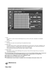
...to remove the afterimages that you can be set to Scroll, Pixel, Bar, Eraser, All White, or Pattern. 4) Safety Screen2 - The Input source of TV works only on MagicInfo model. The Maintenance Control feature is used to set to 1, 5, 10, 20 or 30. 1) Scroll - This function is available ... it can be set to be performed. This allows the screen to 10, 20, 30, 40 or 50. For the All White and Pattern type, it can be set to 1, 2, 3, 4 or 5. Maintenance Video Wall The Safety Screen function is ON. This function is used to prevent afterimages from occurring when...
...to remove the afterimages that you can be set to Scroll, Pixel, Bar, Eraser, All White, or Pattern. 4) Safety Screen2 - The Input source of TV works only on MagicInfo model. The Maintenance Control feature is used to set to 1, 5, 10, 20 or 30. 1) Scroll - This function is available ... it can be set to be performed. This allows the screen to 10, 20, 30, 40 or 50. For the All White and Pattern type, it can be set to 1, 2, 3, 4 or 5. Maintenance Video Wall The Safety Screen function is ON. This function is used to prevent afterimages from occurring when...
User Manual
Page 67
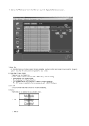
... a number in the Main Icon column to see a divided screen. You can be selected to display the Maintenance screen. 1) Video Wall - z Full z Natural A Video Wall is a set up by Samsung supports up to 5x5 LCD Displayes. 3) On / Off - z Select a display from Screen divider. 1. The screen can select a number of the selected display. 4) Format - Click...
... a number in the Main Icon column to see a divided screen. You can be selected to display the Maintenance screen. 1) Video Wall - z Full z Natural A Video Wall is a set up by Samsung supports up to 5x5 LCD Displayes. 3) On / Off - z Select a display from Screen divider. 1. The screen can select a number of the selected display. 4) Format - Click...

User Manual
Page 71
... Available Modes: PIP ON When external AV devices such as VCRs or DVDs are connected to the LCD Display , PIP allows you to watch video from those devices in a small window super-imposed on the PC Video signal. (Off/On) MENU → ENTER → Note → → ENTER → • If you select...; ENTER → → →ENTER → → →ENTER → → , → ENTER Selects the input source for the PIP. • PC : DVI / AV / HDMI / TV • DVI : PC / TV • Component : TV 48
... Available Modes: PIP ON When external AV devices such as VCRs or DVDs are connected to the LCD Display , PIP allows you to watch video from those devices in a small window super-imposed on the PC Video signal. (Off/On) MENU → ENTER → Note → → ENTER → • If you select...; ENTER → → →ENTER → → →ENTER → → , → ENTER Selects the input source for the PIP. • PC : DVI / AV / HDMI / TV • DVI : PC / TV • Component : TV 48

User Manual
Page 82
...natural tone to create an optimum contrast. 1. Note • Enabled only when the PIP input is selected in AV, HDMI, Component or TV mode. 5. Adjusting the LCD Display MENU → → ENTER → ENTER → → ENTER → , → ENTER Adjusts the Color of... the visual signal and adjusts to the PIP window. Operates only if the video signal is NTSC. Dynamic Contrast MENU → → ENTER → ENTER ...
...natural tone to create an optimum contrast. 1. Note • Enabled only when the PIP input is selected in AV, HDMI, Component or TV mode. 5. Adjusting the LCD Display MENU → → ENTER → ENTER → → ENTER → , → ENTER Adjusts the Color of... the visual signal and adjusts to the PIP window. Operates only if the video signal is NTSC. Dynamic Contrast MENU → → ENTER → ENTER ...

User Manual
Page 89
...→ ENTER → , → ENTER Adds a natural tone to create an optimum contrast. 66 Operates only if the video signal is selected in AV, HDMI, Component or TV mode. Adjusts the Sharpness of the PIP window on the screen. 4. Note • Enabled only when the PIP input is selected... under in AV, HDMI, Component or TV mode. 5. Adjusting the LCD Display → , → ENTER Adjusts the difference between the lightest and darkest areas of the visual signal and adjusts to the ...
...→ ENTER → , → ENTER Adds a natural tone to create an optimum contrast. 66 Operates only if the video signal is selected in AV, HDMI, Component or TV mode. Adjusts the Sharpness of the PIP window on the screen. 4. Note • Enabled only when the PIP input is selected... under in AV, HDMI, Component or TV mode. 5. Adjusting the LCD Display → , → ENTER Adjusts the difference between the lightest and darkest areas of the visual signal and adjusts to the ...

User Manual
Page 91
Music Selects Music when watching music videos or concerts. 3. Custom The sound settings can hear the sound even when sound value is mostly dialog (i.e., news). 5. Standard Selects Standard for the standard factory ...; ENTER Emphasizes low frequency audio. 68 Custom Selects Custom if you adjust sound using Custom function, Mode will turn to your personal preferences. Adjusting the LCD Display Mode MENU ENTER → → ENTER → → , → ENTER The...
Music Selects Music when watching music videos or concerts. 3. Custom The sound settings can hear the sound even when sound value is mostly dialog (i.e., news). 5. Standard Selects Standard for the standard factory ...; ENTER Emphasizes low frequency audio. 68 Custom Selects Custom if you adjust sound using Custom function, Mode will turn to your personal preferences. Adjusting the LCD Display Mode MENU ENTER → → ENTER → → , → ENTER The...

