Quick Guide (easy Manual) (ver.1.0) (Korean)
Page 2
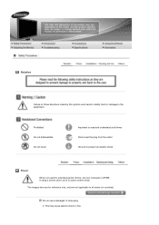
Do not use a damaged or loose plug. The images here are for extended period of time, set your computer to DPMS. If using a screen saver, set it to the equipment. Prohibited Do not disassemble Do not touch Important to read and understand at all cases (or countries). This may cause electric shock or fire. Notation Failure to follow directions noted by this symbol could result in all times Disconnect the plug from the outlet Ground to prevent an electric shock Power When not used for reference only, and are not applicable in bodily harm or damage to active screen mode.
Do not use a damaged or loose plug. The images here are for extended period of time, set your computer to DPMS. If using a screen saver, set it to the equipment. Prohibited Do not disassemble Do not touch Important to read and understand at all cases (or countries). This may cause electric shock or fire. Notation Failure to follow directions noted by this symbol could result in all times Disconnect the plug from the outlet Ground to prevent an electric shock Power When not used for reference only, and are not applicable in bodily harm or damage to active screen mode.

Service Manual
Page 4
Reference Infomation ...14-1 14-1 Technical Terms ...14-1 14-2 Pin Assignments ...14-4 14-3 Timing Chart ...14-5 14-4 Preset Timing Modes ...14-6 14-5 Panel Description ...14-7 Disassembly and Reassembly ...11-1 11-1 Disassembly ...11-1 11-2 Reassembly ...11-3 12. Operating Instructions and Installation ...10-1 10-1 Front ...10-1 10-2 Rear ...10-2 10-3 Using the Stand ...10-4 11. PCB...
Reference Infomation ...14-1 14-1 Technical Terms ...14-1 14-2 Pin Assignments ...14-4 14-3 Timing Chart ...14-5 14-4 Preset Timing Modes ...14-6 14-5 Panel Description ...14-7 Disassembly and Reassembly ...11-1 11-1 Disassembly ...11-1 11-2 Reassembly ...11-3 12. Operating Instructions and Installation ...10-1 10-1 Front ...10-1 10-2 Rear ...10-2 10-3 Using the Stand ...10-4 11. PCB...
Service Manual
Page 6
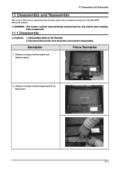
Use caution when handling these components. 11-1 Disassembly Cautions: 1. Disassembly stand on the flat desk. 2. Description Picture Description 1. Remove 3 screws from the power source before disassembly. Disconnect the monitor from the stand and Remove stand. 2. Remove 3 screws from the stand and Lift up back cover. 11-1 11 Disassembly and Reassembly 11 Disassembly and Reassembly This section of the service manual describes the disassembly and reassembly procedures for the LHA20WS TFT-LCD monitors. WARNING: This monitor contains electrostatically sensitive devices.
Use caution when handling these components. 11-1 Disassembly Cautions: 1. Disassembly stand on the flat desk. 2. Description Picture Description 1. Remove 3 screws from the power source before disassembly. Disconnect the monitor from the stand and Remove stand. 2. Remove 3 screws from the stand and Lift up back cover. 11-1 11 Disassembly and Reassembly 11 Disassembly and Reassembly This section of the service manual describes the disassembly and reassembly procedures for the LHA20WS TFT-LCD monitors. WARNING: This monitor contains electrostatically sensitive devices.
Service Manual
Page 7
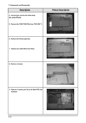
Use the jig to remove the shield lamp. (Be careful Shield.) 5. Picture Description 6. Remove the Panel Lamp wire. 7. Remove 4 screws. 9. Remove the LVDS Wire from PCB ASS'Y. Remove the FUNCTION Wire from Panel. 8. 11 Disassembly and Reassembly Description 4. Remove 4 screws and Lift up the Main PCB and IB Board. 11-2
Use the jig to remove the shield lamp. (Be careful Shield.) 5. Picture Description 6. Remove the Panel Lamp wire. 7. Remove 4 screws. 9. Remove the LVDS Wire from PCB ASS'Y. Remove the FUNCTION Wire from Panel. 8. 11 Disassembly and Reassembly Description 4. Remove 4 screws and Lift up the Main PCB and IB Board. 11-2
Service Manual
Page 9
11 Disassembly and Reassembly 11-2 Reassembly Reassembly procedures are in the reverse order of disassembly procedures. 11-4
11 Disassembly and Reassembly 11-2 Reassembly Reassembly procedures are in the reverse order of disassembly procedures. 11-4
Service Manual
Page 75
... Infomation ...14-1 14-1 Technical Terms ...14-1 14-2 Pin Assignments ...14-4 14-3 Timing Chart ...14-5 14-4 Preset Timing Modes ...14-6 14-5 Panel Description ...14-7 Disassembly and Reassembly ...11-1 11-1 Disassembly ...11-1 11-2 Reassembly ...11-3 12. Circuit Descriptions ...13-1 13-1 Block description ...13-1 13-2 Block operating ...13-2 14. Wiring Diagram ...8-1 9. Schematic Diagrams ...9-1 9-1 Schematic Diagrams...
... Infomation ...14-1 14-1 Technical Terms ...14-1 14-2 Pin Assignments ...14-4 14-3 Timing Chart ...14-5 14-4 Preset Timing Modes ...14-6 14-5 Panel Description ...14-7 Disassembly and Reassembly ...11-1 11-1 Disassembly ...11-1 11-2 Reassembly ...11-3 12. Circuit Descriptions ...13-1 13-1 Block description ...13-1 13-2 Block operating ...13-2 14. Wiring Diagram ...8-1 9. Schematic Diagrams ...9-1 9-1 Schematic Diagrams...

