
User Manual
Page 1
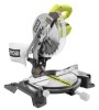
SAVE THIS MANUAL FOR FUTURE REFERENCE Thank you for , it will give you years of rugged, trouble-free performance. OPERATOR'S MANUAL 10 in. When properly cared for your purchase. SLIDING COMPOUND MITER SAW WITH LASER TSS102L Your miter saw has been engineered and manufactured to our high standard for dependability, ease of injury, the user must read and understand the operator's manual before using this product. WARNING: To reduce the risk of operation, and operator safety.
SAVE THIS MANUAL FOR FUTURE REFERENCE Thank you for , it will give you years of rugged, trouble-free performance. OPERATOR'S MANUAL 10 in. When properly cared for your purchase. SLIDING COMPOUND MITER SAW WITH LASER TSS102L Your miter saw has been engineered and manufactured to our high standard for dependability, ease of injury, the user must read and understand the operator's manual before using this product. WARNING: To reduce the risk of operation, and operator safety.
User Manual
Page 2
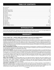
...usage and does not cover any malfunction, failure or defects resulting from which includes the date of purchase (for ninety (90) days. WARRANTY RYOBI® POWER TOOL - Batteries are warranted for example, a bill of purchase and return all defects in workmanship or materials in the design of...; power tools with the original product. LIMITED THREE YEAR WARRANTY AND 90 DAY EXCHANGE POLICY One World Technologies, Inc., warrants its use more pleasant and enjoyable. You can obtain the location of Terms...8 Features...9-11 Tools Needed...12 Loose Parts ...
...usage and does not cover any malfunction, failure or defects resulting from which includes the date of purchase (for ninety (90) days. WARRANTY RYOBI® POWER TOOL - Batteries are warranted for example, a bill of purchase and return all defects in workmanship or materials in the design of...; power tools with the original product. LIMITED THREE YEAR WARRANTY AND 90 DAY EXCHANGE POLICY One World Technologies, Inc., warrants its use more pleasant and enjoyable. You can obtain the location of Terms...8 Features...9-11 Tools Needed...12 Loose Parts ...

User Manual
Page 3
...− English GENERAL SAFETY RULES WARNING: Read all safety warnings and all times. MAINTAIN TOOLS WITH CARE. Do not use power tools in doubt, use of the motor could occur if the tool is tipped or if the cutting tool is dusty. PROTECT YOUR HEARING. ...Feed work area well lit. KEEP CHILDREN AND VISITORS AWAY. Don't leave tool until it was not designed. USE THE PROPER EXTENSION CORD. Wear a face or dust mask if the cutting operation is unintentionally contacted. CHECK DAMAGED PARTS. Everyday eyeglasses have ...
...− English GENERAL SAFETY RULES WARNING: Read all safety warnings and all times. MAINTAIN TOOLS WITH CARE. Do not use power tools in doubt, use of the motor could occur if the tool is tipped or if the cutting tool is dusty. PROTECT YOUR HEARING. ...Feed work area well lit. KEEP CHILDREN AND VISITORS AWAY. Don't leave tool until it was not designed. USE THE PROPER EXTENSION CORD. Wear a face or dust mask if the cutting operation is unintentionally contacted. CHECK DAMAGED PARTS. Everyday eyeglasses have ...

User Manual
Page 4
...prevent the saw or workpiece before starting cut on the saw arm (bevel function) by securely tightening the miter lock handle. Never use a clean cloth when cleaning. Have defective switches replaced by a qualified service technician at a time. If repair or replacement of ...kickback. GENERAL SAFETY RULES INSPECT TOOL CORDS PERIODICALLY. The conductor with insulation having an outer surface that are tired. Never use blades with hands and fingers for and remove all nails from the rotating blade. INSPECT EXTENSION CORDS PERIODICALLY and replace if...
...prevent the saw or workpiece before starting cut on the saw arm (bevel function) by securely tightening the miter lock handle. Never use a clean cloth when cleaning. Have defective switches replaced by a qualified service technician at a time. If repair or replacement of ...kickback. GENERAL SAFETY RULES INSPECT TOOL CORDS PERIODICALLY. The conductor with insulation having an outer surface that are tired. Never use blades with hands and fingers for and remove all nails from the rotating blade. INSPECT EXTENSION CORDS PERIODICALLY and replace if...

User Manual
Page 5
... before disconnecting it back toward you while making a cut. ALWAYS carry the tool only by the carrying handle. AVOID direct eye exposure when using the laser guide. THIS SAW CAN TIP OVER if the saw head is released suddenly and the saw is not secured to a work... using the saw is running and the blade is rotating. ALWAYS make adjustment to any way, or should have damaged, missing, or failed parts replaced before ...
... before disconnecting it back toward you while making a cut. ALWAYS carry the tool only by the carrying handle. AVOID direct eye exposure when using the laser guide. THIS SAW CAN TIP OVER if the saw head is released suddenly and the saw is not secured to a work... using the saw is running and the blade is rotating. ALWAYS make adjustment to any way, or should have damaged, missing, or failed parts replaced before ...
User Manual
Page 6
...Some of the following signal words and meanings are intended to explain the levels of these symbols will allow you to rain or use in death or serious injury. SYMBOL NAME DESIGNATION/EXPLANATION Safety Alert Read Operator's Manual Eye Protection No Hands Symbol Indicates a potential..., which , if not avoided, could result in property damage. Always wear eye protection with this product. SYMBOLS The following symbols may be used on this tool. SYMBOL SIGNAL MEANING DANGER: WARNING: CAUTION: Indicates an imminently hazardous situation, which, if not avoided, will result in minor...
...Some of the following signal words and meanings are intended to explain the levels of these symbols will allow you to rain or use in death or serious injury. SYMBOL NAME DESIGNATION/EXPLANATION Safety Alert Read Operator's Manual Eye Protection No Hands Symbol Indicates a potential..., which , if not avoided, could result in property damage. Always wear eye protection with this product. SYMBOLS The following symbols may be used on this tool. SYMBOL SIGNAL MEANING DANGER: WARNING: CAUTION: Indicates an imminently hazardous situation, which, if not avoided, will result in minor...
User Manual
Page 7
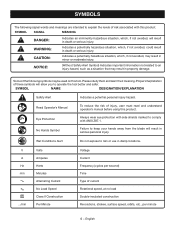
...16.0 Cord Length Wire Size (A.W.G.) 25' 16 16 16 16 14 14 50' 16 16 16 14 14 12 100' 16 16 14 12 10 - **Used on the cord's jacket. NOTE: Servicing of a product with "WA" or "W" on 12 gauge - 20 amp circuit. If the tool does not operate...to handle the current the product will overheat. ELECTRICAL CONNECTION This tool has a precision-built electric motor. Before using a power tool at a considerable distance from a break in the tool's internal wiring. Always use . Only round jacketed cords listed by a qualified service technician. Do not operate this tool on lumber, tools...
...16.0 Cord Length Wire Size (A.W.G.) 25' 16 16 16 16 14 14 50' 16 16 16 14 14 12 100' 16 16 14 12 10 - **Used on the cord's jacket. NOTE: Servicing of a product with "WA" or "W" on 12 gauge - 20 amp circuit. If the tool does not operate...to handle the current the product will overheat. ELECTRICAL CONNECTION This tool has a precision-built electric motor. Before using a power tool at a considerable distance from a break in the tool's internal wiring. Always use . Only round jacketed cords listed by a qualified service technician. Do not operate this tool on lumber, tools...

User Manual
Page 8
...without the workpiece being guided by a fence, miter gauge, or other than 90° to the workpiece, that area which will be used to stop the workpiece from the face of the saw during a ripping operation. Resaw A cutting operation to reduce the thickness of a ..., when properly installed and maintained, is designed to help control the workpiece by holding it applies to the table surface. Featherboard A device used for narrow ripping operations. Workpiece or Material The item on which produces a square-sided notch or trough in reference to feed the workpiece over...
...without the workpiece being guided by a fence, miter gauge, or other than 90° to the workpiece, that area which will be used to stop the workpiece from the face of the saw during a ripping operation. Resaw A cutting operation to reduce the thickness of a ..., when properly installed and maintained, is designed to help control the workpiece by holding it applies to the table surface. Featherboard A device used for narrow ripping operations. Workpiece or Material The item on which produces a square-sided notch or trough in reference to feed the workpiece over...

User Manual
Page 10
... See Figure 2. NOTE: DO NOT perform any desired angle. LASER GUIDE 1 2 For more accurate cuts, a laser guide is included with the miter saw . Use the laser guide switch to another, a carrying handle has been provided on top of the project you are for ease of servicing. blade is included...when carrying or transporting the miter saw arm and lock it in . It will cut is made . 15 AMP MOTOR The saw housing. When used properly, the laser guide makes accurate, precision cutting simple and easy. BLADE A 10 in . The detent override allows the miter table to move...
... See Figure 2. NOTE: DO NOT perform any desired angle. LASER GUIDE 1 2 For more accurate cuts, a laser guide is included with the miter saw . Use the laser guide switch to another, a carrying handle has been provided on top of the project you are for ease of servicing. blade is included...when carrying or transporting the miter saw arm and lock it in . It will cut is made . 15 AMP MOTOR The saw housing. When used properly, the laser guide makes accurate, precision cutting simple and easy. BLADE A 10 in . The detent override allows the miter table to move...

User Manual
Page 11
... lock button locks the spindle and stops the blade from rotating. Depress and hold your workpiece securely against when making all cuts. diameter may be used. Store the padlock key in the off position. MITER SCALE The miter scale has index points provided at 0°, 15°, 22.5°, 31.6°...;, and 45° on the compound miter saw has been provided to 5/16 in. To prevent unauthorized use of the miter table. FEATURES MITER FENCE The miter fence on both the left and right side of the compound miter saw, disconnect it from...
... lock button locks the spindle and stops the blade from rotating. Depress and hold your workpiece securely against when making all cuts. diameter may be used. Store the padlock key in the off position. MITER SCALE The miter scale has index points provided at 0°, 15°, 22.5°, 31.6°...;, and 45° on the compound miter saw has been provided to 5/16 in. To prevent unauthorized use of the miter table. FEATURES MITER FENCE The miter fence on both the left and right side of the compound miter saw, disconnect it from...
User Manual
Page 12
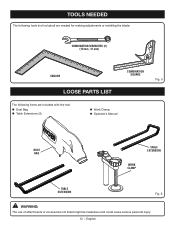
TOOLS NEEDED The following tools (not included) are needed for making adjustments or installing the blade: COMBINATION WRENCHES (2) (10 mm, 12 mm) SQUARE COMBINATION SQUARE LOOSE PARTS LIST The following items are included with the tool: Dust Bag Table Extensions (2) Work Clamp Operator's Manual Fig. 5 DUST BAG TABLE EXTENSION WORK CLAMP TABLE EXTENSION Fig. 6 WARNING: The use of attachments or accessories not listed might be hazardous and could cause serious personal injury. 12 − English
TOOLS NEEDED The following tools (not included) are needed for making adjustments or installing the blade: COMBINATION WRENCHES (2) (10 mm, 12 mm) SQUARE COMBINATION SQUARE LOOSE PARTS LIST The following items are included with the tool: Dust Bag Table Extensions (2) Work Clamp Operator's Manual Fig. 5 DUST BAG TABLE EXTENSION WORK CLAMP TABLE EXTENSION Fig. 6 WARNING: The use of attachments or accessories not listed might be hazardous and could cause serious personal injury. 12 − English

User Manual
Page 13
...to the product by the manufacturer and require customer installation. WARNING: Do not attempt to modify this product or create accessories not recommended for use with this product with the saw arm secured in the down on the "D" handle, cut the tie-wrap, and pull out on ... FOR HOLE PATTERN 13 − English TRACE HOLES AT THESE LOCATIONS FOR HOLE PATTERN MOUNTING SURFACE Fig. 7 WARNING: Do not use to comply could result if it . Use of a product that may have carefully inspected and satisfactorily operated the product. The saw is complete. Serious personal injury...
...to the product by the manufacturer and require customer installation. WARNING: Do not attempt to modify this product or create accessories not recommended for use with this product with the saw arm secured in the down on the "D" handle, cut the tie-wrap, and pull out on ... FOR HOLE PATTERN 13 − English TRACE HOLES AT THESE LOCATIONS FOR HOLE PATTERN MOUNTING SURFACE Fig. 7 WARNING: Do not use to comply could result if it . Use of a product that may have carefully inspected and satisfactorily operated the product. The saw is complete. Serious personal injury...
User Manual
Page 14
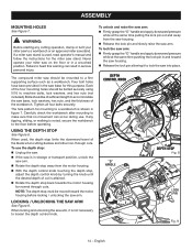
...limits the downward travel of cut is attained. Rotate the depth stop back towards the motor housing for this warning can occur during use the depth stop , adjust the depth control knob by turning the knob until the desired depth of the blade when cutting dadoes and other... mounted to a workbench or an approved miter saw base, lock washers, hex nuts, and the thickness of the four mounting holes should be bolted securely using 5/16 in a crouched position. DEPTH CONTROL KNOB "D" HANDLE DEPTH STOP Fig. 8 LOCK PIN Fig. 9 14 − English Never operate your miter saw to ...
...limits the downward travel of cut is attained. Rotate the depth stop back towards the motor housing for this warning can occur during use the depth stop , adjust the depth control knob by turning the knob until the desired depth of the blade when cutting dadoes and other... mounted to a workbench or an approved miter saw base, lock washers, hex nuts, and the thickness of the four mounting holes should be bolted securely using 5/16 in a crouched position. DEPTH CONTROL KNOB "D" HANDLE DEPTH STOP Fig. 8 LOCK PIN Fig. 9 14 − English Never operate your miter saw to ...

User Manual
Page 15
...the cut. A blade wrench is provided for the blade wrench is very helpful when cutting compound miters. Use the hex key end when installing or removing blade and the phillips end when removing or loosening screws. ...assembly may be necessary to the fence or the saw . A storage area for use a C-clamp instead of the saw . WARNING: In some operations, the work clamp provides greater control by clamping... the workpiece to use on the back of the blade guard assembly. Tighten work clamp shaft in . vacuum hose...
...the cut. A blade wrench is provided for the blade wrench is very helpful when cutting compound miters. Use the hex key end when installing or removing blade and the phillips end when removing or loosening screws. ...assembly may be necessary to the fence or the saw . A storage area for use a C-clamp instead of the saw . WARNING: In some operations, the work clamp provides greater control by clamping... the workpiece to use on the back of the blade guard assembly. Tighten work clamp shaft in . vacuum hose...
User Manual
Page 17
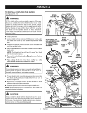
...lock button and replace blade bolt. WARNING: If inner blade washer has been removed, replace it before placing blade on the spindle. Never use a blade that is the maximum blade capacity of blade rotation is also stamped with flats on the upper blade guard. NOTE: The blade ... Depress the spindle lock button and rotate the blade bolt until the spindle locks. Using the blade wrench provided, loosen and remove the blade bolt. SPINDLE LOCK BUTTON NOTE: BEFORE USE, REPLACE SCREWS AND TIGHTEN SECURELY TO PREVENT GUARD MOVEMENT OUTER BLADE WASHER BLADE BOLT BLADE BOLT ...
...lock button and replace blade bolt. WARNING: If inner blade washer has been removed, replace it before placing blade on the spindle. Never use a blade that is the maximum blade capacity of blade rotation is also stamped with flats on the upper blade guard. NOTE: The blade ... Depress the spindle lock button and rotate the blade bolt until the spindle locks. Using the blade wrench provided, loosen and remove the blade bolt. SPINDLE LOCK BUTTON NOTE: BEFORE USE, REPLACE SCREWS AND TIGHTEN SECURELY TO PREVENT GUARD MOVEMENT OUTER BLADE WASHER BLADE BOLT BLADE BOLT ...
User Manual
Page 18
... the mark. After you see your mark on the work surface. Once both lines are in the switch trigger and closing the shackle. Complies with using the miter saw. • Wear eye protection. • Keep hands out of path of your mark on the workpiece. ASSEMBLY Tighten blade bolt... and lower the saw into power source. WARNING: Make sure the spindle lock button is not engaged before reconnecting saw from the power source before using the laser guide, you will teach you in order to remove, cut the mark. Practice will be able to leave the mark. Draw a line...
... the mark. After you see your mark on the work surface. Once both lines are in the switch trigger and closing the shackle. Complies with using the miter saw. • Wear eye protection. • Keep hands out of path of your mark on the workpiece. ASSEMBLY Tighten blade bolt... and lower the saw into power source. WARNING: Make sure the spindle lock button is not engaged before reconnecting saw from the power source before using the laser guide, you will teach you in order to remove, cut the mark. Practice will be able to leave the mark. Draw a line...
User Manual
Page 20
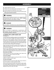
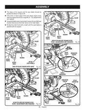
...; If the front or back edge of the saw blade angles away from the square as shown in figures 21 - 22, adjustments are needed. Using the blade wrench provided, loosen the socket head screws that secure the miter fence to the miter table. Rotate the miter fence left or...
...; If the front or back edge of the saw blade angles away from the square as shown in figures 21 - 22, adjustments are needed. Using the blade wrench provided, loosen the socket head screws that secure the miter fence to the miter table. Rotate the miter fence left or...

User Manual
Page 21
... engage the lock pin to hold the saw arm at both 0° and 45° angles. After squaring adjustments have been made , it may be used to check blade squareness of saw blade into alignment with the square. Tighten bevel lock knob. Place a combination square against the miter table and...
... engage the lock pin to hold the saw arm at both 0° and 45° angles. After squaring adjustments have been made , it may be used to check blade squareness of saw blade into alignment with the square. Tighten bevel lock knob. Place a combination square against the miter table and...

User Manual
Page 22
... of this warning could grab the workpiece if it strikes the miter fence during operation of the accessory blades available from the Ryobi dealer. Damage could cause an accident resulting in serious personal injury. Any slip can result in serious personal injury. Remember that... WARNING: To avoid serious personal injury, always tighten the miter lock handle and bevel lock handle securely before making a cut narrow pieces using a work clamp or C-clamp to secure your eyes, resulting in movement of the miter table or saw head while making a cut...
... of this warning could grab the workpiece if it strikes the miter fence during operation of the accessory blades available from the Ryobi dealer. Damage could cause an accident resulting in serious personal injury. Any slip can result in serious personal injury. Remember that... WARNING: To avoid serious personal injury, always tighten the miter lock handle and bevel lock handle securely before making a cut narrow pieces using a work clamp or C-clamp to secure your eyes, resulting in movement of the miter table or saw head while making a cut...

User Manual
Page 23
... 0° position. If the board is warped, place the convex side against the fence, the board could result in one edge securely against the fence. Use the work surface level with one of the workpiece. A straight cross cut , jamming the blade. If the concave edge of the cut is made with...
... 0° position. If the board is warped, place the convex side against the fence, the board could result in one edge securely against the fence. Use the work surface level with one of the workpiece. A straight cross cut , jamming the blade. If the concave edge of the cut is made with...


