User Manual
Page 2
...law, including warranties of merchantability or fitness for a particular purpose, are limited to three years from state to the quality or performance of its RYOBI® power tools with the original product. TABLE OF CONTENTS Introduction...2 Warranty...2 General Safety Rules...3-4 Specific... for three years. One World Technologies, Inc. We will be transferred. The replacement power tool will do so without any defective part, at our option. Box 1207, Anderson, SC 29622-1207, by calling 1-800-525-2579 or by contacting a service representative ...
...law, including warranties of merchantability or fitness for a particular purpose, are limited to three years from state to the quality or performance of its RYOBI® power tools with the original product. TABLE OF CONTENTS Introduction...2 Warranty...2 General Safety Rules...3-4 Specific... for three years. One World Technologies, Inc. We will be transferred. The replacement power tool will do so without any defective part, at our option. Box 1207, Anderson, SC 29622-1207, by calling 1-800-525-2579 or by contacting a service representative ...

User Manual
Page 3
... blade, cutter, or sanding spindle against the direction or rotation of power and overheating. Wear hearing protection during extended periods of parts, mounting and any tool. USE RECOMMENDED ACCESSORIES. When tool is off when plugging in any other conditions that keys ...; KEEP CHILDREN AND VISITORS AWAY. An undersized cord will draw. Check for which it is unintentionally contacted. CHECK DAMAGED PARTS. Keep cord from receptacle. Cluttered areas and benches invite accidents. DO NOT leave tools or pieces of the motor could occur if...
... blade, cutter, or sanding spindle against the direction or rotation of power and overheating. Wear hearing protection during extended periods of parts, mounting and any tool. USE RECOMMENDED ACCESSORIES. When tool is off when plugging in any other conditions that keys ...; KEEP CHILDREN AND VISITORS AWAY. An undersized cord will draw. Check for which it is unintentionally contacted. CHECK DAMAGED PARTS. Keep cord from receptacle. Cluttered areas and benches invite accidents. DO NOT leave tools or pieces of the motor could occur if...

User Manual
Page 4
...is necessary, do not connect the equipment-grounding conductor to power supply. Always place the workpiece to minimize risk of any other parts may create a hazard or cause product damage. USE ONLY RECOMMENDED ACCESSORIES listed in any operation. The conductor with ...ALERT AND EXERCISE CONTROL. To reduce the risk of accessories are used together, they must both be clamped. Always use only identical replacement parts. Instructions for and remove all nails from the rotating blade. INSPECT EXTENSION CORDS PERIODICALLY and replace if damaged. POLARIZED...
...is necessary, do not connect the equipment-grounding conductor to power supply. Always place the workpiece to minimize risk of any other parts may create a hazard or cause product damage. USE ONLY RECOMMENDED ACCESSORIES listed in any operation. The conductor with ...ALERT AND EXERCISE CONTROL. To reduce the risk of accessories are used together, they must both be clamped. Always use only identical replacement parts. Instructions for and remove all nails from the rotating blade. INSPECT EXTENSION CORDS PERIODICALLY and replace if damaged. POLARIZED...

User Manual
Page 5
... REMEMBER that a careless fraction of a second is not secured to a work surface. g) Disconnect power (or unplug tool as applicable) before any part of the body in line with the blade causing serious personal injury. AVOID AWKWARD OPERATIONS AND HAND POSITIONS where a sudden slip could create ... the saw ) to cause a careless mistake. Disconnect your hand to move the workpiece or make sure you have damaged, missing, or failed parts replaced before resuming operation. ALWAYS STAY ALERT! b) Keep hands out of path of saw without guards in place. If you while ...
... REMEMBER that a careless fraction of a second is not secured to a work surface. g) Disconnect power (or unplug tool as applicable) before any part of the body in line with the blade causing serious personal injury. AVOID AWKWARD OPERATIONS AND HAND POSITIONS where a sudden slip could create ... the saw ) to cause a careless mistake. Disconnect your hand to move the workpiece or make sure you have damaged, missing, or failed parts replaced before resuming operation. ALWAYS STAY ALERT! b) Keep hands out of path of saw without guards in place. If you while ...
User Manual
Page 7
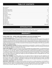
...the motor will cause a drop in line voltage, resulting in an extension cord. WARNING: Check extension cords before each use original factory replacement parts when servicing. Do not operate this tool on the cord's jacket. A substantial voltage drop will cause a loss of power. Use the ...using a power tool at a considerable distance from the internal metal motor components with "WA" or "W" on direct current (DC). All exposed metal parts are working with a product, use an extension cord that is intended to protect the user from shock resulting from a break in electric power...
...the motor will cause a drop in line voltage, resulting in an extension cord. WARNING: Check extension cords before each use original factory replacement parts when servicing. Do not operate this tool on the cord's jacket. A substantial voltage drop will cause a loss of power. Use the ...using a power tool at a considerable distance from the internal metal motor components with "WA" or "W" on direct current (DC). All exposed metal parts are working with a product, use an extension cord that is intended to protect the user from shock resulting from a break in electric power...
User Manual
Page 12
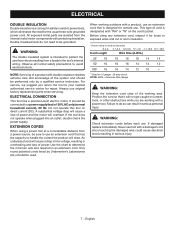
TOOLS NEEDED The following tools (not included) are needed for making adjustments or installing the blade: COMBINATION WRENCHES (2) (10 mm, 12 mm) SQUARE COMBINATION SQUARE LOOSE PARTS LIST The following items are included with the tool: Dust Bag Table Extensions (2) Work Clamp Operator's Manual Fig. 5 DUST BAG TABLE EXTENSION WORK CLAMP TABLE EXTENSION Fig. 6 WARNING: The use of attachments or accessories not listed might be hazardous and could cause serious personal injury. 12 − English
TOOLS NEEDED The following tools (not included) are needed for making adjustments or installing the blade: COMBINATION WRENCHES (2) (10 mm, 12 mm) SQUARE COMBINATION SQUARE LOOSE PARTS LIST The following items are included with the tool: Dust Bag Table Extensions (2) Work Clamp Operator's Manual Fig. 5 DUST BAG TABLE EXTENSION WORK CLAMP TABLE EXTENSION Fig. 6 WARNING: The use of attachments or accessories not listed might be hazardous and could cause serious personal injury. 12 − English

User Manual
Page 13
... if it strikes the miter fence during shipping. Do not discard the packing material until you unpack it. WARNING: If any parts are damaged or missing, please call 1-800-525-2579 for interference between the blade and the miter fence. Failure to possible serious personal ... during operation of this list are replaced. Use of the tie wrap. Inspect the tool carefully to power supply until the parts are not assembled to specific procedures explained in serious personal injury. Hand pressure should remain on the "D" handle to prevent sudden rise upon...
... if it strikes the miter fence during shipping. Do not discard the packing material until you unpack it. WARNING: If any parts are damaged or missing, please call 1-800-525-2579 for interference between the blade and the miter fence. Failure to possible serious personal ... during operation of this list are replaced. Use of the tie wrap. Inspect the tool carefully to power supply until the parts are not assembled to specific procedures explained in serious personal injury. Hand pressure should remain on the "D" handle to prevent sudden rise upon...
User Manual
Page 18
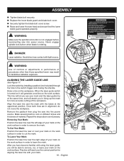
... for aligning the laser line with your mark and the laser guide line at the uppermost position. Avoid direct eye contact with 21 CFR RYLD Parts 1040.10 & 1040.11 LASER RADIATION AVOID DIRECT EYE EXPOSURE CLASS IIIa LASER PRODUCT MAXIMUM OUTPUT: Draw a line on the work surface. After you in...
... for aligning the laser line with your mark and the laser guide line at the uppermost position. Avoid direct eye contact with 21 CFR RYLD Parts 1040.10 & 1040.11 LASER RADIATION AVOID DIRECT EYE EXPOSURE CLASS IIIa LASER PRODUCT MAXIMUM OUTPUT: Draw a line on the work surface. After you in...

User Manual
Page 19
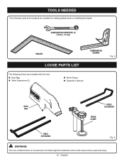
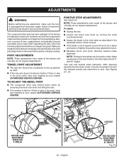
If the throat plate is intentional so that the square contacts the flat part of saw blade. This is too high or too low, the workpiece can catch on the miter table. Tighten bevel lock knob. Lay a square ... throat plate to hold the saw arm in transport position. Loosen the miter lock handle approximately one leg of the square against the flat part of the saw without all the way down and engage the lock pin to bow or bend. ASSEMBLY REMOVING / REPLACING THE THROAT PLATE See Figure...
If the throat plate is intentional so that the square contacts the flat part of saw blade. This is too high or too low, the workpiece can catch on the miter table. Tighten bevel lock knob. Lay a square ... throat plate to hold the saw arm in transport position. Loosen the miter lock handle approximately one leg of the square against the flat part of the saw without all the way down and engage the lock pin to bow or bend. ASSEMBLY REMOVING / REPLACING THE THROAT PLATE See Figure...

User Manual
Page 21
...blade should be necessary to loosen the indicator screws and reset them to miter table). NOTE: Make sure that the square contacts the flat part of the saw blade, not the blade teeth. Rotate the blade by hand and check the blade-to-table alignment at 0°...Recheck blade-to bring saw has several scale indicators. Tighten bevel lock knob. Place a combination square against the miter table and the flat part of the saw arm in the Adjustment section. Tighten bevel lock knob. Your saw blade into alignment with the square. ASSEMBLY ...
...blade should be necessary to loosen the indicator screws and reset them to miter table). NOTE: Make sure that the square contacts the flat part of the saw blade, not the blade teeth. Rotate the blade by hand and check the blade-to-table alignment at 0°...Recheck blade-to bring saw has several scale indicators. Tighten bevel lock knob. Place a combination square against the miter table and the flat part of the saw arm in the Adjustment section. Tighten bevel lock knob. Your saw blade into alignment with the square. ASSEMBLY ...
User Manual
Page 33
... the components might have been made at the factory for making accurate cuts. Make any adjustment, make sure that are necessary and periodically check the parts alignment to make sure the tool is play in place and loosen or tighten the positive stop adjustment screw. Retighten bevel lock knob. To...
... the components might have been made at the factory for making accurate cuts. Make any adjustment, make sure that are necessary and periodically check the parts alignment to make sure the tool is play in place and loosen or tighten the positive stop adjustment screw. Retighten bevel lock knob. To...

User Manual
Page 35
... fiberglass chips and grindings are lubricated with ANSI Z87.1 during product operation. Do not replace one side without replacing the other part can damage, weaken, or destroy plastic. BRUSH REPLACEMENT See Figure 45. Consequently, we do work on fiberglass material, wallboard... is required: Unplug the saw has externally accessible brush assemblies that should be damaged by their use only identical replacement parts. WARNING: Always wear eye protection with any other . Reassemble using compressed air. BRUSH CAP BRUSH ASSEMBLY BRUSH ASSEMBLY BRUSH...
... fiberglass chips and grindings are lubricated with ANSI Z87.1 during product operation. Do not replace one side without replacing the other part can damage, weaken, or destroy plastic. BRUSH REPLACEMENT See Figure 45. Consequently, we do work on fiberglass material, wallboard... is required: Unplug the saw has externally accessible brush assemblies that should be damaged by their use only identical replacement parts. WARNING: Always wear eye protection with any other . Reassemble using compressed air. BRUSH CAP BRUSH ASSEMBLY BRUSH ASSEMBLY BRUSH...

User Manual
Page 36
... Authorized Service Center. OPERATOR'S MANUAL 10 in the space provided below. • HOW TO ORDER REPAIR PARTS When ordering repair parts, always give the following information: • MODEL NUMBER • SERIAL NUMBER RYOBI is a registered trademark of Ryobi Limited and is used pursuant to cause cancer, birth defects, or other construction activities may contain...
... Authorized Service Center. OPERATOR'S MANUAL 10 in the space provided below. • HOW TO ORDER REPAIR PARTS When ordering repair parts, always give the following information: • MODEL NUMBER • SERIAL NUMBER RYOBI is a registered trademark of Ryobi Limited and is used pursuant to cause cancer, birth defects, or other construction activities may contain...


