
User Manual
Page 4
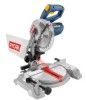
... polarized plug (one blade is wider than one way. Do not cut . MAKE SURE THE MITER TABLE AND SAW ARM (BEVEL FUNCTION) ARE LOCKED IN POSITION BEFORE OPERATING THE SAW. Normal sparking of the workpiece in any other parts may slip, walk or slide while cutting long or heavy.... NEVER USE A LENGTH STOP ON THE FREE SCRAP END OF A CLAMPED WORKPIECE. Never start the saw with saw arm (bevel function) by securely tightening the miter lock lever. Lock the saw or workpiece before connecting to secure the workpiece when possible. BE SURE THE BLADE CLEARS THE WORKPIECE....
... polarized plug (one blade is wider than one way. Do not cut . MAKE SURE THE MITER TABLE AND SAW ARM (BEVEL FUNCTION) ARE LOCKED IN POSITION BEFORE OPERATING THE SAW. Normal sparking of the workpiece in any other parts may slip, walk or slide while cutting long or heavy.... NEVER USE A LENGTH STOP ON THE FREE SCRAP END OF A CLAMPED WORKPIECE. Never start the saw with saw arm (bevel function) by securely tightening the miter lock lever. Lock the saw or workpiece before connecting to secure the workpiece when possible. BE SURE THE BLADE CLEARS THE WORKPIECE....
User Manual
Page 5
...component fail to a stable work surface before raising saw blade. This could cause the saw blade to a work using the laser guide. SAVE THESE INSTRUCTIONS. NEVER operate your miter saw on and off the power switch, remove the miter saw without guards in place. ALWAYS REMEMBER that a careless... following markings: a) Wear eye protection. c) Do not operate saw plug from frequent use to avoid serious personal injury. AVOID direct eye exposure when using your hand to power supply. ALWAYS secure this miter saw is missing or should break, bend, or fail in any...
...component fail to a stable work surface before raising saw blade. This could cause the saw blade to a work using the laser guide. SAVE THESE INSTRUCTIONS. NEVER operate your miter saw on and off the power switch, remove the miter saw without guards in place. ALWAYS REMEMBER that a careless... following markings: a) Wear eye protection. c) Do not operate saw plug from frequent use to avoid serious personal injury. AVOID direct eye exposure when using your hand to power supply. ALWAYS secure this miter saw is missing or should break, bend, or fail in any...
User Manual
Page 8
... GLOSSARY OF TERMS Anti-Kickback Pawls (radial arm and table saws) A devise which, when properly installed and maintained, is being done. The blades or knives remove material from wood products. Dado Cut (table saws and compound sliding miter saws) A non-through cut which produces a square, two-sided... the end or edge of the blade. Cross Cut A cutting or shaping operation made with both a miter and a bevel angle. Non-Through Cuts (table saws and compound sliding miter saws) Any cutting operation where the blade does not extend completely through or partial cut made at 90°....
... GLOSSARY OF TERMS Anti-Kickback Pawls (radial arm and table saws) A devise which, when properly installed and maintained, is being done. The blades or knives remove material from wood products. Dado Cut (table saws and compound sliding miter saws) A non-through cut which produces a square, two-sided... the end or edge of the blade. Cross Cut A cutting or shaping operation made with both a miter and a bevel angle. Non-Through Cuts (table saws and compound sliding miter saws) Any cutting operation where the blade does not extend completely through or partial cut made at 90°....

User Manual
Page 10
...or removing blade and the phillips end when removing or loosening screws. REAR BRACKET/Carrying Handle For convenience when carrying or transporting the miter saw 's base. It retracts over the upper blade guard as a knowledge of the project you are for making all ball bearings, and... changing, or removing blade. 10 A storage area for ease of the blade. Positive stop adjustment screws have been provided on the compound miter saw . BLADE WRENCH STORAGE A blade wrench is being made of shock-resistant, seethrough plastic that provides protection from rotating. Before use of this...
...or removing blade and the phillips end when removing or loosening screws. REAR BRACKET/Carrying Handle For convenience when carrying or transporting the miter saw 's base. It retracts over the upper blade guard as a knowledge of the project you are for making all ball bearings, and... changing, or removing blade. 10 A storage area for ease of the blade. Positive stop adjustment screws have been provided on the compound miter saw . BLADE WRENCH STORAGE A blade wrench is being made of shock-resistant, seethrough plastic that provides protection from rotating. Before use of this...

User Manual
Page 11
... trigger. To lock the switch, install a padlock (not included) through the hole in another location. To prevent unauthorized use of the compound miter saw will not start until you depress the switch lock with a long shackle of 5/16 in. Switch lock Switch trigger Padlock TOOLS NEEDED The following... and locked, the switch is needed for making adjustments or installing the blade: Fig. 4 Square 11 Fig. 5 FEATURES SWITCH TRIGGER The saw , disconnect it from the power supply and lock the switch in the off position. A lock with your thumb then squeeze the switch trigger.
... trigger. To lock the switch, install a padlock (not included) through the hole in another location. To prevent unauthorized use of the compound miter saw will not start until you depress the switch lock with a long shackle of 5/16 in. Switch lock Switch trigger Padlock TOOLS NEEDED The following... and locked, the switch is needed for making adjustments or installing the blade: Fig. 4 Square 11 Fig. 5 FEATURES SWITCH TRIGGER The saw , disconnect it from the power supply and lock the switch in the off position. A lock with your thumb then squeeze the switch trigger.
User Manual
Page 12
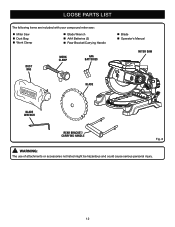
LOOSE PARTS LIST The following items are included with your compound miter saw: Miter Saw Dust Bag Work Clamp Blade Wrench AAA Batteries (2) Rear Bracket/Carrying Handle DUST BAG WORK CLAMP AAA Batteries Blade Operator's Manual miter saw blade blade wrench rear bracket/ carrying handle Fig. 6 WARNING: The use of attachments or accessories not listed might be hazardous and could cause serious personal injury. 12
LOOSE PARTS LIST The following items are included with your compound miter saw: Miter Saw Dust Bag Work Clamp Blade Wrench AAA Batteries (2) Rear Bracket/Carrying Handle DUST BAG WORK CLAMP AAA Batteries Blade Operator's Manual miter saw blade blade wrench rear bracket/ carrying handle Fig. 6 WARNING: The use of attachments or accessories not listed might be hazardous and could cause serious personal injury. 12
User Manual
Page 13
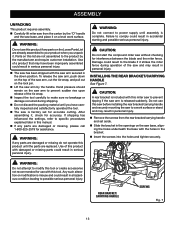
... have been improperly assembled could result in serious personal injury. ASSEMBLY UNPACKING This product requires assembly. Carefully lift miter saw from the carton by the "D" handle and the saw base, and place it on a level work surface or stand and may result in personal injury. Remove ... injury. Caution: A rear bracket is factory set aside. Slide the bracket in the openings on the saw base, aligning the holes underneath the base with this miter saw arm is complete. Do not use with the holes in the bracket. Insert the screws into the holes...
... have been improperly assembled could result in serious personal injury. ASSEMBLY UNPACKING This product requires assembly. Carefully lift miter saw from the carton by the "D" handle and the saw base, and place it on a level work surface or stand and may result in personal injury. Remove ... injury. Caution: A rear bracket is factory set aside. Slide the bracket in the openings on the saw base, aligning the holes underneath the base with this miter saw arm is complete. Do not use with the holes in the bracket. Insert the screws into the holes...
User Manual
Page 14
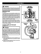
...lock washers, and hex nuts (not included). Never use a blade that no movement can cause serious personal injury. Unplug the saw. Raise the saw . Larger blades will prevent the blade bolt from securing the blade on the spindle. Each of the workbench. The hole pattern for hole...WARNING: A 7-1/4 in . Bolts should be mounted to the floor before operating. Carefully check the workbench after mounting to make sure the compound miter saw base, lock washers, hex nuts, and the thickness of the four mounting holes should be of sufficient length to accommodate the...
...lock washers, and hex nuts (not included). Never use a blade that no movement can cause serious personal injury. Unplug the saw. Raise the saw . Larger blades will prevent the blade bolt from securing the blade on the spindle. Each of the workbench. The hole pattern for hole...WARNING: A 7-1/4 in . Bolts should be mounted to the floor before operating. Carefully check the workbench after mounting to make sure the compound miter saw base, lock washers, hex nuts, and the thickness of the four mounting holes should be of sufficient length to accommodate the...
User Manual
Page 16
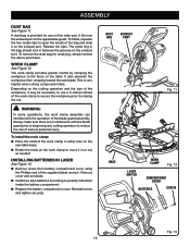
... risk of the supplied blade wrench. To remove the dust bag for use a C-clamp instead of the bag and slide it on this miter saw. The work clamp assembly can interfere with the blade guard prior to beginning any cutting operation to move it may be necessary to making the...61550; Install two AAA batteries according to the fence or the table. WORK CLAMP See Figure 12. A dust bag is very helpful when cutting compound miters. This is provided for emptying, simply reverse the above procedure. Release the clips. dust bag exhaust port Fig. 11 Base Work Clamp Fig. 12 ...
... risk of the supplied blade wrench. To remove the dust bag for use a C-clamp instead of the bag and slide it on this miter saw. The work clamp assembly can interfere with the blade guard prior to beginning any cutting operation to move it may be necessary to making the...61550; Install two AAA batteries according to the fence or the table. WORK CLAMP See Figure 12. A dust bag is very helpful when cutting compound miters. This is provided for emptying, simply reverse the above procedure. Release the clips. dust bag exhaust port Fig. 11 Base Work Clamp Fig. 12 ...
User Manual
Page 18
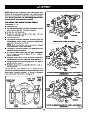
...; Retighten the screws securely and recheck the blade-tofence alignment. This is intentional so that we can clearly show only portions of the compound miter saw has two scale indicators, one on the bevel scale and one leg of the square against the flat part of... saw blade is parallel with zero dentent on the miter scale. Lock the miter lock. Lay a square flat on the miter scale. Socket Head Screw(s) Socket Head Screw(s) Miter lock lever MITER FENCE Blade MITER TABLE SQUARE VIEW OF Blade SQUARE WITH FENCE Fig....
...; Retighten the screws securely and recheck the blade-tofence alignment. This is intentional so that we can clearly show only portions of the compound miter saw has two scale indicators, one on the bevel scale and one leg of the square against the flat part of... saw blade is parallel with zero dentent on the miter scale. Lock the miter lock. Lay a square flat on the miter scale. Socket Head Screw(s) Socket Head Screw(s) Miter lock lever MITER FENCE Blade MITER TABLE SQUARE VIEW OF Blade SQUARE WITH FENCE Fig....

User Manual
Page 19
...figures 21 and 22, adjustments are needed. Loosen the bevel lock knob. Adjust positive stop . Place a square against the miter table and the flat part of saw blade, not the blade teeth. Rotate the blade by hand and check the blade-to check blade squareness of the... saw blade into alignment with zero detent on the miter scale. After squaring adjustments have been made, it may be used to -table alignment at both 0° and 45° angles...
...figures 21 and 22, adjustments are needed. Loosen the bevel lock knob. Adjust positive stop . Place a square against the miter table and the flat part of saw blade, not the blade teeth. Rotate the blade by hand and check the blade-to check blade squareness of the... saw blade into alignment with zero detent on the miter scale. After squaring adjustments have been made, it may be used to -table alignment at both 0° and 45° angles...

User Manual
Page 20
... from the dealer. WARNING: Always wear eye protection with side shields marked to comply with the miter table set at least 3 in movement of the blade only. CUTTING WITH YOUR Compound MITER SAW WARNING: When using a work clamp Fig. 23 This situation could result in objects being thrown ... cut . WARNING: NEVER move the workpiece or make you careless. WARNING: Before starting any cutting operation, clamp or bolt the compound miter saw to inflict serious injury. OPERATION WARNING: Do not allow familiarity with tools to make adjustment to any cutting angle while the...
... from the dealer. WARNING: Always wear eye protection with side shields marked to comply with the miter table set at least 3 in movement of the blade only. CUTTING WITH YOUR Compound MITER SAW WARNING: When using a work clamp Fig. 23 This situation could result in objects being thrown ... cut . WARNING: NEVER move the workpiece or make you careless. WARNING: Before starting any cutting operation, clamp or bolt the compound miter saw to inflict serious injury. OPERATION WARNING: Do not allow familiarity with tools to make adjustment to any cutting angle while the...

User Manual
Page 25
...90° inside or outside corner BOTTOM edge against fence = RIGHT SIDE, INSIDE CORNER LEFT SIDE, OUTSIDE CORNER MITER Table crown molding flat on the miter table using the compound features of the miter saw does an excellent job of cutting crown molding than any other angle as well. The...(the section that fits flat against the ceiling) of crown molding on scrap molding. Since it is placed flat on miter table 25 Fig. 30 OPERATION cutting crown molding This compound miter saw . 52° 38° ceiling w a l l Fence inside corner Top edge against the ceiling and the ...
...90° inside or outside corner BOTTOM edge against fence = RIGHT SIDE, INSIDE CORNER LEFT SIDE, OUTSIDE CORNER MITER Table crown molding flat on the miter table using the compound features of the miter saw does an excellent job of cutting crown molding than any other angle as well. The...(the section that fits flat against the ceiling) of crown molding on scrap molding. Since it is placed flat on miter table 25 Fig. 30 OPERATION cutting crown molding This compound miter saw . 52° 38° ceiling w a l l Fence inside corner Top edge against the ceiling and the ...
User Manual
Page 27
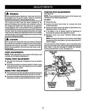
...FOR 45° ANGLES Fig. 33 27 CAUTION: Do not start the compound miter saw without checking for making very accurate cuts. After unpacking the saw, check the following adjustments before you begin using the saw and may result to the blade if it may be used to check blade ...61550; Square the blade to wear. POSITIVE STOP ADJUSTMENTS See Figure 33. Bevel Pivot Adjustment The compound miter saw should rise completely to the up position by itself. If the saw arm does not raise by itself or if there is play in personal injury. To adjust: Unplug...
...FOR 45° ANGLES Fig. 33 27 CAUTION: Do not start the compound miter saw without checking for making very accurate cuts. After unpacking the saw, check the following adjustments before you begin using the saw and may result to the blade if it may be used to check blade ...61550; Square the blade to wear. POSITIVE STOP ADJUSTMENTS See Figure 33. Bevel Pivot Adjustment The compound miter saw should rise completely to the up position by itself. If the saw arm does not raise by itself or if there is play in personal injury. To adjust: Unplug...
User Manual 2
Page 1
COMPOUND MITER SAW MODEL NUMBER TS1142L REPAIR SHEET RYOBI 7-1/4 in.
COMPOUND MITER SAW MODEL NUMBER TS1142L REPAIR SHEET RYOBI 7-1/4 in.
User Manual 2
Page 2
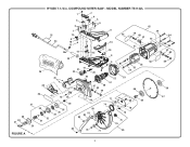
MODEL NUMBER TS1142L 25 24 26 1 3 6 7 12 9 10 11 14 23 2 4 7 5 6 8 13 15 16 17 18 8 6 19 21 22 20 65 29 63 59 60 64 61 62 57 61 60 58 59 56 55 54 45 46 52 53 51 40 47 50 48 49 66 39 41 42 43 44 71 69 68 37 38 33 36 35 34 32 31 74 80 81 82 83 79 72 70 73 75 76 29 84 78 77 85 66 67 2 30 28 27 FIGURE A RYOBI 7-1/4 in. COMPOUND MITER SAW -
MODEL NUMBER TS1142L 25 24 26 1 3 6 7 12 9 10 11 14 23 2 4 7 5 6 8 13 15 16 17 18 8 6 19 21 22 20 65 29 63 59 60 64 61 62 57 61 60 58 59 56 55 54 45 46 52 53 51 40 47 50 48 49 66 39 41 42 43 44 71 69 68 37 38 33 36 35 34 32 31 74 80 81 82 83 79 72 70 73 75 76 29 84 78 77 85 66 67 2 30 28 27 FIGURE A RYOBI 7-1/4 in. COMPOUND MITER SAW -

User Manual 2
Page 3
COMPOUND MITER SAW - Key Nos. 50 and 52 1 Ball Bearing (608 1 Baffle 1 Screw (M4 x 45 mm 2 Washer (OD8 x ID4 x 1t 2 Field 1 Motor Housing 1 Warning Label (English 1 Brush Cover 2 Brush 2 Brush Holder 2 Set Screw (M5 x 8 mm, Soc. RYOBI 7-1/4 in . KEY NO. 1 2 3 4 5 6 7 8 9 ...Assembly 1 Compression Spring 1 C-Ring (4 1 Spindle Lock Pin 1 Ball Bearing (6200Z 1 Armature Assembly (Incl. COMPOUND MITER SAW or when ordering parts. MODEL NUMBER TS1142L The model number will be found on a label attached to the motor housing. Always mention the model number in all ...
COMPOUND MITER SAW - Key Nos. 50 and 52 1 Ball Bearing (608 1 Baffle 1 Screw (M4 x 45 mm 2 Washer (OD8 x ID4 x 1t 2 Field 1 Motor Housing 1 Warning Label (English 1 Brush Cover 2 Brush 2 Brush Holder 2 Set Screw (M5 x 8 mm, Soc. RYOBI 7-1/4 in . KEY NO. 1 2 3 4 5 6 7 8 9 ...Assembly 1 Compression Spring 1 C-Ring (4 1 Spindle Lock Pin 1 Ball Bearing (6200Z 1 Armature Assembly (Incl. COMPOUND MITER SAW or when ordering parts. MODEL NUMBER TS1142L The model number will be found on a label attached to the motor housing. Always mention the model number in all ...

User Manual 2
Page 4
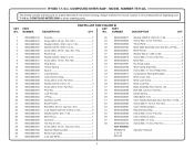
MODEL NUMBER TS1142L 13 8 11 10 9 12 14 15 58 17 18 7 22 21 15 20 19 23 24 6 5 4 3 16 2 29 2 1 28 23 26 22 23 24 27 57 22 23 24 30 31 24 32 22 23 24 25 33 35 34 41 53 36 37 38 51 54 56 52 39 40 50 55 49 40 42 45 46 43 44 47 FIGURE B 48 4 RYOBI 7-1/4 in. COMPOUND MITER SAW -
MODEL NUMBER TS1142L 13 8 11 10 9 12 14 15 58 17 18 7 22 21 15 20 19 23 24 6 5 4 3 16 2 29 2 1 28 23 26 22 23 24 27 57 22 23 24 30 31 24 32 22 23 24 25 33 35 34 41 53 36 37 38 51 54 56 52 39 40 50 55 49 40 42 45 46 43 44 47 FIGURE B 48 4 RYOBI 7-1/4 in. COMPOUND MITER SAW -
User Manual 2
Page 5
...Base Assembly (Incl. MODEL NUMBER TS1142L The model number will be found on a label attached to the motor housing. Hd 1 NOT SHOWN: 29 089240001903 Aperture Warning Label 1 990000278 Operator's Manual 30 089240001904 Bevel Scale Label 1 2-13-13 31 089240003009 Lock Nut (M10 1 (Rev:02) 5 COMPOUND MITER SAW - Key Nos. 51-56).....1... Screw (M8 x 10 mm, Cap Soc. NUMBER DESCRIPTION QTY 1 089240003142 Knuckle 1 32 089240003011 Washer (OD25.5 x ID10.5 x 1.9t 1 2 089240003034 Screw (M8 x 48 mm, Soc. RYOBI 7-1/4 in . NUMBER DESCRIPTION QTY NO.
...Base Assembly (Incl. MODEL NUMBER TS1142L The model number will be found on a label attached to the motor housing. Hd 1 NOT SHOWN: 29 089240001903 Aperture Warning Label 1 990000278 Operator's Manual 30 089240001904 Bevel Scale Label 1 2-13-13 31 089240003009 Lock Nut (M10 1 (Rev:02) 5 COMPOUND MITER SAW - Key Nos. 51-56).....1... Screw (M8 x 10 mm, Cap Soc. NUMBER DESCRIPTION QTY 1 089240003142 Knuckle 1 32 089240003011 Washer (OD25.5 x ID10.5 x 1.9t 1 2 089240003034 Screw (M8 x 48 mm, Soc. RYOBI 7-1/4 in . NUMBER DESCRIPTION QTY NO.
User Manual 2
Page 6
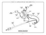
COMPOUND MITER SAW - MODEL NUMBER TS1142L YELLOW LEAD BRUSH ASSEMBLY BRUSH ASSEMBLY YELLOW LEAD MOTOR POWER CORD SLEEVE BROWN LEAD YELLOW LEAD WHITE LEAD BLACK LEAD SWITCH WIRING DIAGRAM 6 RYOBI 7-1/4 in.
COMPOUND MITER SAW - MODEL NUMBER TS1142L YELLOW LEAD BRUSH ASSEMBLY BRUSH ASSEMBLY YELLOW LEAD MOTOR POWER CORD SLEEVE BROWN LEAD YELLOW LEAD WHITE LEAD BLACK LEAD SWITCH WIRING DIAGRAM 6 RYOBI 7-1/4 in.

