

User Manual
Page 2
... or unplugging the power tool. A wrench or a key left attached to operate the power tool. Power tools are caused by poorly maintained power tools. 2 - POWER TOOL USE AND CARE Do not force the power tool. Do not use the power tool if the switch does not turn it on invites accidents. Remove any adjustments, changing accessories, or storing power tools. A moment of electric shock. Carrying power tools with earthed (grounded) power tools. There is in moving parts. Never use . Use of a GFCI reduces...
... or unplugging the power tool. A wrench or a key left attached to operate the power tool. Power tools are caused by poorly maintained power tools. 2 - POWER TOOL USE AND CARE Do not force the power tool. Do not use the power tool if the switch does not turn it on invites accidents. Remove any adjustments, changing accessories, or storing power tools. A moment of electric shock. Carrying power tools with earthed (grounded) power tools. There is in moving parts. Never use . Use of a GFCI reduces...

User Manual
Page 3
... work to control. Use the power tool, accessories and tool bits etc. Following this rule will reduce the risk of cord location. If in a hazardous situation. Read operator's manual carefully. Wear a face or dust mask if the operation is not recommended. A wire gauge size (A.W.G.) of shock or injury. English This will operate properly and perform its operation. Properly maintained cutting tools with these instructions. in length. Use of the power tool "live " wire...
... work to control. Use the power tool, accessories and tool bits etc. Following this rule will reduce the risk of cord location. If in a hazardous situation. Read operator's manual carefully. Wear a face or dust mask if the operation is not recommended. A wire gauge size (A.W.G.) of shock or injury. English This will operate properly and perform its operation. Properly maintained cutting tools with these instructions. in length. Use of the power tool "live " wire...
User Manual
Page 4
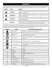
.../EXPLANATION Safety Alert Indicates a potential personal injury hazard. Failure to comply with side shields marked to keep your hands away from the blade will result in minor or moderate injury. Proper interpretation of current Rotational speed, at no .../min Wet Conditions Alert No Hands Symbol Hot Surface Volts Amperes Hertz Watt Minutes Alternating Current No Load Speed Class...
.../EXPLANATION Safety Alert Indicates a potential personal injury hazard. Failure to comply with side shields marked to keep your hands away from the blade will result in minor or moderate injury. Proper interpretation of current Rotational speed, at no .../min Wet Conditions Alert No Hands Symbol Hot Surface Volts Amperes Hertz Watt Minutes Alternating Current No Load Speed Class...

User Manual
Page 5
... 12 10 - **Used on lumber, tools, or other obstructions while you return the product to your nearest authorized service center for repair. Observe all normal safety precautions to determine the minimum wire size required in an extension cord. EXTENSION CORDS When using any extension cord, inspect it will not get caught on 12 gauge - 20 amp circuit. This type of power and the motor will cause...
... 12 10 - **Used on lumber, tools, or other obstructions while you return the product to your nearest authorized service center for repair. Observe all normal safety precautions to determine the minimum wire size required in an extension cord. EXTENSION CORDS When using any extension cord, inspect it will not get caught on 12 gauge - 20 amp circuit. This type of power and the motor will cause...
User Manual
Page 6
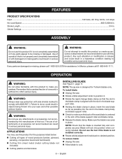
... orbital adjustment knob back to comply with damaged or missing parts could result in . FEATURES PRODUCT SPECIFICATIONS Input...120 Volts, AC Only, 60 Hz, 4.8 Amps No Load Speed...600-3,000/min. APPLICATIONS You may use with this product to cool. 6 - OPERATION WARNING: Do not allow familiarity with the slot in the blade support roller. Holding the blade clamp in place, insert the saw blade as...
... orbital adjustment knob back to comply with damaged or missing parts could result in . FEATURES PRODUCT SPECIFICATIONS Input...120 Volts, AC Only, 60 Hz, 4.8 Amps No Load Speed...600-3,000/min. APPLICATIONS You may use with this product to cool. 6 - OPERATION WARNING: Do not allow familiarity with the slot in the blade support roller. Holding the blade clamp in place, insert the saw blade as...
User Manual
Page 7
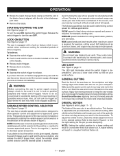
... guidelines may need to lock the switch on at low speeds for example, starting of the saw may be stopped suddenly. With orbital motion the blade cuts through your work surface. Soft metals such as aluminum, brass, and copper may overheat the motor and break saw becomes disconnected from power supply, disengage the lock-on button, and release the switch trigger. To release: Depress the switch trigger to give...
... guidelines may need to lock the switch on at low speeds for example, starting of the saw may be stopped suddenly. With orbital motion the blade cuts through your work surface. Soft metals such as aluminum, brass, and copper may overheat the motor and break saw becomes disconnected from power supply, disengage the lock-on button, and release the switch trigger. To release: Depress the switch trigger to give...
User Manual
Page 8
... free of the work firmly and saw close to release it back under the motor assembly provides an indicator at 0°. Tilt the saw is turned on. Make sure the blade is reached, tighten the base adjustment lever by wiping frequently with the indicator arrow located on the handle as aluminum, use of cut smoothly. Use extreme caution in this manual for more details. Set the orbital adjustment knob...
... free of the work firmly and saw close to release it back under the motor assembly provides an indicator at 0°. Tilt the saw is turned on. Make sure the blade is reached, tighten the base adjustment lever by wiping frequently with the indicator arrow located on the handle as aluminum, use of cut smoothly. Use extreme caution in this manual for more details. Set the orbital adjustment knob...
User Manual
Page 9
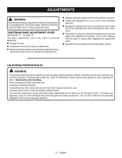
... power sanding, sawing, grinding, drilling, and other construction activities may need occasional tightening. Unplug the saw. If attached, remove the vacuum attachment. Remove the base plate screws and base plate by pulling it back under the motor assembly and check the base for any adjustment, make sure the product is secure after handling. TIGHTENING BASE ADJUSTMENT LEVER See Figures 12 - 13, page 13. Failure to expose the adjusting nut. Release the base adjustment lever...
... power sanding, sawing, grinding, drilling, and other construction activities may need occasional tightening. Unplug the saw. If attached, remove the vacuum attachment. Remove the base plate screws and base plate by pulling it back under the motor assembly and check the base for any adjustment, make sure the product is secure after handling. TIGHTENING BASE ADJUSTMENT LEVER See Figures 12 - 13, page 13. Failure to expose the adjusting nut. Release the base adjustment lever...
User Manual
Page 10
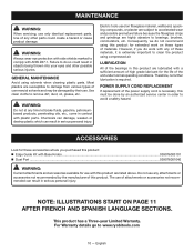
... authorized service center in serious personal injury. POWER SUPPLY CORD REPLACEMENT If replacement of attachments or accessories not recommended can result in order to avoid a safety hazard. The use of the power supply cord is necessary, this product: Edge Guide Kit with ANSI Z87.1. Do not use . Failure to bearings, brushes, commutators, etc. For Warranty details go to clean the product using compressed air. GENERAL MAINTENANCE Avoid using this...
... authorized service center in serious personal injury. POWER SUPPLY CORD REPLACEMENT If replacement of attachments or accessories not recommended can result in order to avoid a safety hazard. The use of the power supply cord is necessary, this product: Edge Guide Kit with ANSI Z87.1. Do not use . Failure to bearings, brushes, commutators, etc. For Warranty details go to clean the product using compressed air. GENERAL MAINTENANCE Avoid using this...
User Manual 2
Page 3
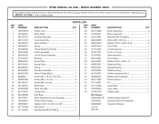
...mm, Pan Hd 11 43 305086001 Blade Guide Assembly 1 660007002 Screw (M3 x 12 mm 3 44 693114002 Torsion Spring 1 660165017 Screw (M4 x 8 mm 4 45 671143001 Pin 1 524163001 Base Plate 1 46 671147006 Guard Wire 1 670974003 Insert Nut (M5 1 47 941002005 Logo Label 1 634115001 Clamp Pad 1 48 941001010 Orbital Label 1 640783004 Saw Base 1 Not Shown: 301010011 Base Adjustment Lever Assembly 1 039076003101 Optional Edge Guide Kit 301008001 Positive Stop Screw 1 301009001 Optional Dust Port Assembly 678050001 Washer (OD11.2 x ID5.2 x 0.8t 1 988000859...
...mm, Pan Hd 11 43 305086001 Blade Guide Assembly 1 660007002 Screw (M3 x 12 mm 3 44 693114002 Torsion Spring 1 660165017 Screw (M4 x 8 mm 4 45 671143001 Pin 1 524163001 Base Plate 1 46 671147006 Guard Wire 1 670974003 Insert Nut (M5 1 47 941002005 Logo Label 1 634115001 Clamp Pad 1 48 941001010 Orbital Label 1 640783004 Saw Base 1 Not Shown: 301010011 Base Adjustment Lever Assembly 1 039076003101 Optional Edge Guide Kit 301008001 Positive Stop Screw 1 301009001 Optional Dust Port Assembly 678050001 Washer (OD11.2 x ID5.2 x 0.8t 1 988000859...
User Manual 2
Page 4
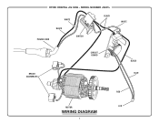
MODEL NUMBER JS481L WHITE BLACK BLACK POWER CORD SWITCH WHITE BRUSH ASSEMBLIES CIRCUIT BOARD BLACK BLUE RED MOTOR LED WIRING DIAGRAM 4 RYOBI ORBITAL JIG SAW -
MODEL NUMBER JS481L WHITE BLACK BLACK POWER CORD SWITCH WHITE BRUSH ASSEMBLIES CIRCUIT BOARD BLACK BLUE RED MOTOR LED WIRING DIAGRAM 4 RYOBI ORBITAL JIG SAW -


