
English Manual
Page 3
..., radiators, ranges, refrigerator enclosures. KEEP GUARDS IN PLACE and in working order. REMOVE ADJUSTING KEYS AND WRENCHES. Be sure switch is off when plugging in good condition. An undersized cord will operate properly and perform its operation. Keep cord away from blades. Do not reach... as the specific potential hazards related to this tool. GUARD AGAINST ELECTRICAL SHOCK by preventing body contact with padlocks and master switches, or by an authorized service center to do the job better and safer at the feed rate for which it will cause a ...
..., radiators, ranges, refrigerator enclosures. KEEP GUARDS IN PLACE and in working order. REMOVE ADJUSTING KEYS AND WRENCHES. Be sure switch is off when plugging in good condition. An undersized cord will operate properly and perform its operation. Keep cord away from blades. Do not reach... as the specific potential hazards related to this tool. GUARD AGAINST ELECTRICAL SHOCK by preventing body contact with padlocks and master switches, or by an authorized service center to do the job better and safer at the feed rate for which it will cause a ...

English Manual
Page 4
...instead of accessories are not completely understood or if in place over the blade while blade is driven back towards the operator. Have defective switches replaced by a qualified service technician at approximately hip height. NEVER OPERATE THE SAW ON THE FLOOR. GUARD AGAINST... WHEN ANY ROTATiNG COMPONENT IS IN CONTACT WITH THE WORKPIECE. DO NOT operate A tool while under the influence of blade path and turn switch off . NEVER USE IN AN EXPLOSIVE ATMOSPHERE. NEVER use a push stick, so your hand into a three-hole electrical receptacle. ...
...instead of accessories are not completely understood or if in place over the blade while blade is driven back towards the operator. Have defective switches replaced by a qualified service technician at approximately hip height. NEVER OPERATE THE SAW ON THE FLOOR. GUARD AGAINST... WHEN ANY ROTATiNG COMPONENT IS IN CONTACT WITH THE WORKPIECE. DO NOT operate A tool while under the influence of blade path and turn switch off . NEVER USE IN AN EXPLOSIVE ATMOSPHERE. NEVER use a push stick, so your hand into a three-hole electrical receptacle. ...
English Manual
Page 10
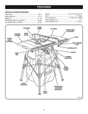
... 46 lbs. spreader outfeed support sliding table extension MITER gauge BLADE GUARD FRONT RAIL RIP FENCE sliding table extension SCALE table locking lever LOCKING LEver SWITCH STORAGE BRACKET(S) BEVEL LOCKING LEVER BEVEL INDICATOR BEVEL SCALE HEIGHT/bevel ADJUSTING HANDWHEEL 10 Fig. 2 Net Weight With Leg Stand 56 lbs. FEATURES PRODUCT SPECIFICATIONS...
... 46 lbs. spreader outfeed support sliding table extension MITER gauge BLADE GUARD FRONT RAIL RIP FENCE sliding table extension SCALE table locking lever LOCKING LEver SWITCH STORAGE BRACKET(S) BEVEL LOCKING LEVER BEVEL INDICATOR BEVEL SCALE HEIGHT/bevel ADJUSTING HANDWHEEL 10 Fig. 2 Net Weight With Leg Stand 56 lbs. FEATURES PRODUCT SPECIFICATIONS...

English Manual
Page 11
... all operating features and safety rules. The miter gauge aligns the wood for bevel angles easy. MITER GAUGE GROOVEs - OUTFEED SUPPORT - RIP FENCE - SWITCH ASSEMBLY - Bevel angles are attempting. BLADE GUARD - This lever, placed just under the saw blade for height adjustments or blade replacement. The easy-to...- The teeth on the front of kickback. Failure to heed this handwheel to -read scale on the anti-kickback pawls point away from the switch. Grooves run along the top and sides of the cabinet, use with a 36-tooth, 10 in the grooves on each side of the ...
... all operating features and safety rules. The miter gauge aligns the wood for bevel angles easy. MITER GAUGE GROOVEs - OUTFEED SUPPORT - RIP FENCE - SWITCH ASSEMBLY - Bevel angles are attempting. BLADE GUARD - This lever, placed just under the saw blade for height adjustments or blade replacement. The easy-to...- The teeth on the front of kickback. Failure to heed this handwheel to -read scale on the anti-kickback pawls point away from the switch. Grooves run along the top and sides of the cabinet, use with a 36-tooth, 10 in the grooves on each side of the ...
English Manual
Page 12
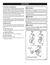
...-kickback pawls, and plastic blade guard. The height of the blade is set with the blade before plugging tool into the switch, lift the switch button to prevent unauthorized and possible hazardous use by an insert called the throat plate. A scale on each side. This feature... and is very important to turn OFF ( O ). FEATURES Operating Components The upper portion of the blade projects up through -sawing operations. POWER SWITCH This saw is not in use the blade guard assembly for the basic cuts: cross cuts, miter cuts, bevel cuts, and compound cuts. WARNING...
...-kickback pawls, and plastic blade guard. The height of the blade is set with the blade before plugging tool into the switch, lift the switch button to prevent unauthorized and possible hazardous use by an insert called the throat plate. A scale on each side. This feature... and is very important to turn OFF ( O ). FEATURES Operating Components The upper portion of the blade projects up through -sawing operations. POWER SWITCH This saw is not in use the blade guard assembly for the basic cuts: cross cuts, miter cuts, bevel cuts, and compound cuts. WARNING...

English Manual
Page 27
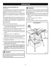
... cut operations. making cross, miter, bevel, and compound miter cuts. Make sure the wood does not touch the blade before use , remove the switch key as shown in kickback which can cause serious personal injury. Never stand directly in the line of cut. Hold the workpiece firmly with... cutoff gauge when cross cutting will result in figure 33. Let the blade build up to full speed before removing the workpiece. 27 SWITCH ON SWITCH OFF SWITCH KEY SWITCH IN LOCKED POSITION Fig. 32 Fig. 33 To secure the angle, lock the miter gauge in personal injury. CROSS CUT PLACE LEFT ...
... cut operations. making cross, miter, bevel, and compound miter cuts. Make sure the wood does not touch the blade before use , remove the switch key as shown in kickback which can cause serious personal injury. Never stand directly in the line of cut. Hold the workpiece firmly with... cutoff gauge when cross cutting will result in figure 33. Let the blade build up to full speed before removing the workpiece. 27 SWITCH ON SWITCH OFF SWITCH KEY SWITCH IN LOCKED POSITION Fig. 32 Fig. 33 To secure the angle, lock the miter gauge in personal injury. CROSS CUT PLACE LEFT ...

English Manual
Page 28
It is recommended you make a test cut past the blade. Add supports to the sides as needed . Turn the power switch to the ON position. Never stand directly in the line of the wood as saw table) behind the saw for the blade to come to a ...; Set the miter gauge to the desired angle and tighten the lock knob. Place a support (the same height as needed . Turn the power switch to avoid serious possible injury. Position the rip fence the desired distance from the blade for the cut See Figure 35. Wait for the...
It is recommended you make a test cut past the blade. Add supports to the sides as needed . Turn the power switch to the ON position. Never stand directly in the line of the wood as saw table) behind the saw for the blade to come to a ...; Set the miter gauge to the desired angle and tighten the lock knob. Place a support (the same height as needed . Turn the power switch to avoid serious possible injury. Position the rip fence the desired distance from the blade for the cut See Figure 35. Wait for the...

English Manual
Page 29
... side of injury should kickback occur. Push the bevel locking lever securely to reduce the chance of the wood as needed. Turn the power switch to avoid possible serious injury. Unlock the bevel locking lever. Remove the rip fence by lifting the locking handle. Turn the height...
... side of injury should kickback occur. Push the bevel locking lever securely to reduce the chance of the wood as needed. Turn the power switch to avoid possible serious injury. Unlock the bevel locking lever. Remove the rip fence by lifting the locking handle. Turn the height...

English Manual
Page 30
... into the blade with the edge flush against the rip fence. Stand to the side of the wood as needed. Turn the power switch to the sides as it . Add supports to the ON position. BEVEL RIP CUT BLADE ANGLED RIP FENCE WARNING: Make sure the blade guard assembly...
... into the blade with the edge flush against the rip fence. Stand to the side of the wood as needed. Turn the power switch to the sides as it . Add supports to the ON position. BEVEL RIP CUT BLADE ANGLED RIP FENCE WARNING: Make sure the blade guard assembly...

English Manual
Page 31
Add supports to the sides as needed . Turn the power switch to the ON position. NOTE: Make sure the wood does not touch the blade before you turn on the saw. NOTE: Make sure the wood ... wood as it contacts the blade to use the rip fence or miter gauge. Add supports to the sides as needed . Turn the power switch to full speed before feeding the workpiece into the blade. Stand to the side of a large panel. Let the blade build up to the...
Add supports to the sides as needed . Turn the power switch to the ON position. NOTE: Make sure the wood does not touch the blade before you turn on the saw. NOTE: Make sure the wood ... wood as it contacts the blade to use the rip fence or miter gauge. Add supports to the sides as needed . Turn the power switch to full speed before feeding the workpiece into the blade. Stand to the side of a large panel. Let the blade build up to the...
English Manual
Page 32
... cut). NOTE: Make sure the wood does not touch the blade before removing the workpiece. Non-through cut such as needed. Turn the power switch to the ON position. WARNING: Never feed wood with your non-through cut is a straight cross cut, read and understand the section on non-through...
... cut). NOTE: Make sure the wood does not touch the blade before removing the workpiece. Non-through cut such as needed. Turn the power switch to the ON position. WARNING: Never feed wood with your non-through cut is a straight cross cut, read and understand the section on non-through...

English Manual
Page 33
... flush against the rip fence. Stand to the side of the wood as it turns freely then lower the blade. Turn the power switch to the ON position. Do not use of 5/8 in . The use an adjustable dado on this tool.
... flush against the rip fence. Stand to the side of the wood as it turns freely then lower the blade. Turn the power switch to the ON position. Do not use of 5/8 in . The use an adjustable dado on this tool.
English Manual
Page 35
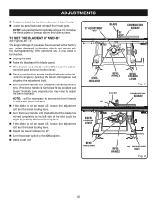
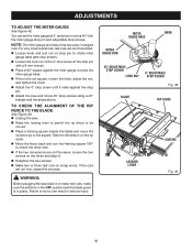
... an exact 45°, loosen the adjustment bolt and the bevel locking lever. Adjust the bevel indicator to 45°. Turn the power switch to bow up above the table surface. ADJUSTMENTS Rotate the blade by hand to make sure it may need to be necessary to remove...
... an exact 45°, loosen the adjustment bolt and the bevel locking lever. Adjust the bevel indicator to 45°. Turn the power switch to bow up above the table surface. ADJUSTMENTS Rotate the blade by hand to make sure it may need to be necessary to remove...
English Manual
Page 36
... pull out on the rip scale. Move the fence back and turn the framing square 180° to make test cuts, make sure the switch is in serious injury.
... pull out on the rip scale. Move the fence back and turn the framing square 180° to make test cuts, make sure the switch is in serious injury.
English Manual
Page 39
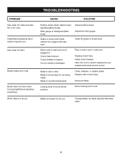
... Miter gauge is blown. Adjust positive stops. Circuit fuse is misaligned (Miter Cuts). Circuit breaker is dull or dirty. Have the cord or switch replaced at full left . Blade is tripped. Replace with saw dust. Saw does not start. Motor labors in rip cut . Blade is not... motor cord or wall cord. rip blade typically has fewer teeth. 39 Reset circuit breaker. Clean the gears or screw post. Cord or switch is mounted backwards. Gears or screw post inside cabinet need adjusting (Bevel Cuts). Change blade; Blade makes poor cuts. Blade is damaged. ...
... Miter gauge is blown. Adjust positive stops. Circuit fuse is misaligned (Miter Cuts). Circuit breaker is dull or dirty. Have the cord or switch replaced at full left . Blade is tripped. Replace with saw dust. Saw does not start. Motor labors in rip cut . Blade is not... motor cord or wall cord. rip blade typically has fewer teeth. 39 Reset circuit breaker. Clean the gears or screw post. Cord or switch is mounted backwards. Gears or screw post inside cabinet need adjusting (Bevel Cuts). Change blade; Blade makes poor cuts. Blade is damaged. ...
Repair Sheet
Page 5
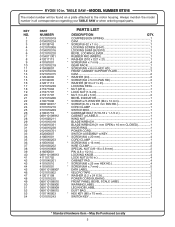
... PANEL BEVEL SCALE LABEL 1 WARNING LABEL 1 LEG KNOB LABEL 4 DUST BAG 1 HEX KEY (M5 x 75 mm 1 SWITCH KEY 1 * Standard Hardware Item - KEY NO. 1 2 3 4 5 6 7 8 9 10 11 12 13... SCREW w/S WASHER (M4 x 12 mm 1 SCREW (8-16 x 19.05 mm PAN HD 2 CORD CLAMP 1 SWITCH BOX 1 CARRIAGE BOLT (5/16-18 x 1-1/2 in 1 CABINET w/LABELS 1 WING NUT 1 BLADE WRENCH 1 BLADE WRENCH (21... mm OPEN x 10 mm CLOSED 1 KNOB RING 1 POWER CORD 1 SWITCH ASSEMBLY w/KEY 1 SCREW (M4 x 20 mm 4 CORD CLAMP 1 SCREW (M4 x 16 mm 4 WIRE CLAMP 2 SPECIAL ...
... PANEL BEVEL SCALE LABEL 1 WARNING LABEL 1 LEG KNOB LABEL 4 DUST BAG 1 HEX KEY (M5 x 75 mm 1 SWITCH KEY 1 * Standard Hardware Item - KEY NO. 1 2 3 4 5 6 7 8 9 10 11 12 13... SCREW w/S WASHER (M4 x 12 mm 1 SCREW (8-16 x 19.05 mm PAN HD 2 CORD CLAMP 1 SWITCH BOX 1 CARRIAGE BOLT (5/16-18 x 1-1/2 in 1 CABINET w/LABELS 1 WING NUT 1 BLADE WRENCH 1 BLADE WRENCH (21... mm OPEN x 10 mm CLOSED 1 KNOB RING 1 POWER CORD 1 SWITCH ASSEMBLY w/KEY 1 SCREW (M4 x 20 mm 4 CORD CLAMP 1 SCREW (M4 x 16 mm 4 WIRE CLAMP 2 SPECIAL ...


