
English Manual
Page 1
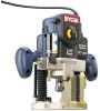
WARNING: To reduce the risk of operation, and operator safety. SAVE THIS MANUAL FOR FUTURE REFERENCE Thank you again for , it will give you years of rugged, trouble-free performance. DOUBLE INSULATED Your new router has been engineered and manufactured to Ryobi's high standard for dependability, ease of injury, the user must read and understand the operator's manual. Properly cared for buying Ryobi tools. OPERATOR'S MANUAL ELECTRONIC PLUNGE ROUTER RE180PL VARIABLE SPEED -
WARNING: To reduce the risk of operation, and operator safety. SAVE THIS MANUAL FOR FUTURE REFERENCE Thank you again for , it will give you years of rugged, trouble-free performance. DOUBLE INSULATED Your new router has been engineered and manufactured to Ryobi's high standard for dependability, ease of injury, the user must read and understand the operator's manual. Properly cared for buying Ryobi tools. OPERATOR'S MANUAL ELECTRONIC PLUNGE ROUTER RE180PL VARIABLE SPEED -
English Manual
Page 6
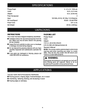
PACKING LIST Plunge Router Collet Adaptor 15/16 in. (23.8 mm) Wrench 5/16-18 UNC-2A Flathead Screws (2) Operator's Manual NOTE: The screws and the optional depth control knob must be used when mounting your router to make sure no breakage or damage occurred during shipping. ■...: If any parts are missing do so could result in the packing list are replaced. Make sure that will secure your router to do not operate your router only for assistance. Plunge Depth Collet Adaptor Peak Horsepower Input No Load Speed Power Cord Net Weight SPECIFICATIONS 0 - 2 in. (0 - 5.08 cm) 1/2...
PACKING LIST Plunge Router Collet Adaptor 15/16 in. (23.8 mm) Wrench 5/16-18 UNC-2A Flathead Screws (2) Operator's Manual NOTE: The screws and the optional depth control knob must be used when mounting your router to make sure no breakage or damage occurred during shipping. ■...: If any parts are missing do so could result in the packing list are replaced. Make sure that will secure your router to do not operate your router only for assistance. Plunge Depth Collet Adaptor Peak Horsepower Input No Load Speed Power Cord Net Weight SPECIFICATIONS 0 - 2 in. (0 - 5.08 cm) 1/2...
English Manual
Page 7
...service, we suggest you reach the desired depth of cut , simply lock the plunge lock lever. FEATURES Your plunge router is a versatile woodworking tool that will then be used for making proper speed selections, your router can be using and to the hardness of the material being cut. SWITCH To ...cutters. It is beautiful and precise. It should be connected to a power supply that is designed for and maintain desired RPM. If your plunge router can be grounded. All exposed metal parts are made when the cutter is a concept in safety in electric power tools, which eliminates the ...
...service, we suggest you reach the desired depth of cut , simply lock the plunge lock lever. FEATURES Your plunge router is a versatile woodworking tool that will then be used for making proper speed selections, your router can be using and to the hardness of the material being cut. SWITCH To ...cutters. It is beautiful and precise. It should be connected to a power supply that is designed for and maintain desired RPM. If your plunge router can be grounded. All exposed metal parts are made when the cutter is a concept in safety in electric power tools, which eliminates the ...

English Manual
Page 9
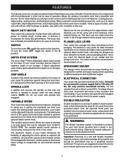
POWER CORD FEATURES REAR VIEW OF ROUTER PLUNGE LOCK LEVER HEX NUT(S) COLLET NUT ROUTER BASE SUBBASE 15 16 15/16 in. (23.8 mm) WRENCH 1/4 in a hazardous condition leading to modify this tool or create accessories not recommended for use with this tool. Any such alteration or modification is misuse and could result in . (6.35 mm) ADAPTOR Fig. 2 WARNING: Do not attempt to possible serious personal injury. 9
POWER CORD FEATURES REAR VIEW OF ROUTER PLUNGE LOCK LEVER HEX NUT(S) COLLET NUT ROUTER BASE SUBBASE 15 16 15/16 in. (23.8 mm) WRENCH 1/4 in a hazardous condition leading to modify this tool or create accessories not recommended for use with this tool. Any such alteration or modification is misuse and could result in . (6.35 mm) ADAPTOR Fig. 2 WARNING: Do not attempt to possible serious personal injury. 9

English Manual
Page 11
... to remove larger amounts of wood in accidental starting causing serious injury. ■ Raise cutter by unlocking plunge lock lever. If you find that extra force is inside router subbase. ■ Place router on router motor. TO LOCK PLUNGE LOCK LEVER TO UNLOCK HEX NUTS DEPTH OF CUT See Figures 5, 6 and 7. Proper depth of cutter...
... to remove larger amounts of wood in accidental starting causing serious injury. ■ Raise cutter by unlocking plunge lock lever. If you find that extra force is inside router subbase. ■ Place router on router motor. TO LOCK PLUNGE LOCK LEVER TO UNLOCK HEX NUTS DEPTH OF CUT See Figures 5, 6 and 7. Proper depth of cutter...

English Manual
Page 12
... ■ Thread depth control knob clockwise onto depth adjustment rod. Do not remove hex nut. WARNING: Failure to unplug your plunge router. WARNING: Relacing optional depth control knob without compression spring could result in accidental starting casuing serious injury. ■ Remove upper hex nut ... with stop . ■ Slide zero-reset indicator up depth adjustment rod, the spring will move 1/8 in. (3.2 mm) from router base. ADJUSTMENTS ■ Lock plunge lock lever to position cutter at "zero" depth of cut. ■ Make sure the hex nuts are securely tightened against hex ...
... ■ Thread depth control knob clockwise onto depth adjustment rod. Do not remove hex nut. WARNING: Failure to unplug your plunge router. WARNING: Relacing optional depth control knob without compression spring could result in accidental starting casuing serious injury. ■ Remove upper hex nut ... with stop . ■ Slide zero-reset indicator up depth adjustment rod, the spring will move 1/8 in. (3.2 mm) from router base. ADJUSTMENTS ■ Lock plunge lock lever to position cutter at "zero" depth of cut. ■ Make sure the hex nuts are securely tightened against hex ...

English Manual
Page 13
...Tighten lock knob securely. See Figure 10. See Figure 11. Always unlock plunge lock lever before routing. ■ Loosen lock knob and adjust stop bar until stop bar comes in successive passes by plunging router until it can be "zero" depth of the Accu-Stop™ MicroAdjustable... Depth Stop System. WARNING: Failure to unplug your router and makes it possible to its uppermost position. ■ Plunge router until cutter reaches the approximate desired depth of cut. ■ Lock plunge lock lever, temporarily locking cutter at each 90° rotation of ...
...Tighten lock knob securely. See Figure 10. See Figure 11. Always unlock plunge lock lever before routing. ■ Loosen lock knob and adjust stop bar until stop bar comes in successive passes by plunging router until it can be "zero" depth of the Accu-Stop™ MicroAdjustable... Depth Stop System. WARNING: Failure to unplug your router and makes it possible to its uppermost position. ■ Plunge router until cutter reaches the approximate desired depth of cut. ■ Lock plunge lock lever, temporarily locking cutter at each 90° rotation of ...

English Manual
Page 14
... scale (A to F) on the variable speed control selector. Then change stop bar position by unlocking plunge lock lever. ■ Place router on flat surface, and lower router until tip of cutter barely touches flat surface. ■ Lock plunge lock lever to position cutter at "zero" depth of cut. ■ Lower stop bar against depth...
... scale (A to F) on the variable speed control selector. Then change stop bar position by unlocking plunge lock lever. ■ Place router on flat surface, and lower router until tip of cutter barely touches flat surface. ■ Lock plunge lock lever to position cutter at "zero" depth of cut. ■ Lower stop bar against depth...

English Manual
Page 15
... guides parallel to the I = ON O = OFF SWITCH Fig. 13 Fig. 14 Fig. 15 Hold the router base against workpiece, and turn the router OFF, toggle the switch to its full speed, then gradually plunge or feed cutter into the workpiece along desired line of cut , place the edge of cut . When... the O position. Position the straightedge parallel to the line of cut in collet nut and that you are doing. Position both sides of the router base. Remain alert and watch what you practice with both hands. ROUTING GROOVES See Figure 15. Clean out any medication. To turn it to...
... guides parallel to the I = ON O = OFF SWITCH Fig. 13 Fig. 14 Fig. 15 Hold the router base against workpiece, and turn the router OFF, toggle the switch to its full speed, then gradually plunge or feed cutter into the workpiece along desired line of cut , place the edge of cut . When... the O position. Position the straightedge parallel to the line of cut in collet nut and that you are doing. Position both sides of the router base. Remain alert and watch what you practice with both hands. ROUTING GROOVES See Figure 15. Clean out any medication. To turn it to...

English Manual
Page 16
... small, intricate details. ■ Rout the pattern in a scrap piece of cut has been made , unlock plunge lock lever, raise cutter inside router subbase, remove router from work surface before the cutter stops. 16 Begin your plunge router becomes a flexible and versatile tool. Upon completion of wood from the same workpiece if possible. ■ Unlock...
... small, intricate details. ■ Rout the pattern in a scrap piece of cut has been made , unlock plunge lock lever, raise cutter inside router subbase, remove router from work surface before the cutter stops. 16 Begin your plunge router becomes a flexible and versatile tool. Upon completion of wood from the same workpiece if possible. ■ Unlock...

English Manual
Page 22
... Make certain clamps can't loosen while in the original locked position. ■ Replace the screw. ■ Check for free plunge with an air jet to unplug your router frequently. After extended use . ✓ Test difficult setups on scrap-Don't waste lumber. ✓ Plan each operation before ... locked position. ■ Remove the screw supporting the plunge lock lever. ■ Remove the lever. ■ Place the lever back in use , the plunge lock may wear. If this happens, you begin. ✓ Clean your router could result in accidental starting causing serious injury. ■...
... Make certain clamps can't loosen while in the original locked position. ■ Replace the screw. ■ Check for free plunge with an air jet to unplug your router frequently. After extended use . ✓ Test difficult setups on scrap-Don't waste lumber. ✓ Plan each operation before ... locked position. ■ Remove the screw supporting the plunge lock lever. ■ Remove the lever. ■ Place the lever back in use , the plunge lock may wear. If this happens, you begin. ✓ Clean your router could result in accidental starting causing serious injury. ■...

English Manual
Page 24
...TO ORDER REPAIR PARTS WHEN ORDERING REPAIR PARTS, ALWAYS GIVE THE FOLLOWING INFORMATION: • MODEL NUMBER RE180PL • SERIAL NUMBER 972000-918 8-02 RYOBI TECHNOLOGIES INC. 1428 Pearman Dairy Road Anderson, SC 29625 Post Office Box 1207 Anderson, SC 29622...Ryobi Authorized Service Center. Only round jacketed cords should a need ever exist for a complete list of power. The model number of the working with a tool outdoors, use an extension cord that has the capacity to use an extension cord that you are working area. OPERATOR'S MANUAL ELECTRONIC PLUNGE ROUTER RE180PL...
...TO ORDER REPAIR PARTS WHEN ORDERING REPAIR PARTS, ALWAYS GIVE THE FOLLOWING INFORMATION: • MODEL NUMBER RE180PL • SERIAL NUMBER 972000-918 8-02 RYOBI TECHNOLOGIES INC. 1428 Pearman Dairy Road Anderson, SC 29625 Post Office Box 1207 Anderson, SC 29622...Ryobi Authorized Service Center. Only round jacketed cords should a need ever exist for a complete list of power. The model number of the working with a tool outdoors, use an extension cord that has the capacity to use an extension cord that you are working area. OPERATOR'S MANUAL ELECTRONIC PLUNGE ROUTER RE180PL...

Repair Sheet
Page 2
...1 STATOR PAD 1 DATA PLATE 1 FIELD 1 BRUSH TUBE 2 BRUSH SET 1 BRUSH CAP 2 BALL BEARING 1 ARMATURE 1 O RING 2 RETAINING RING 1 SPRING WASHER 1 BEARING FRAME 1 PLUNGE LOCK SCREW 1 PLUNGE LOCK LEVER 1 25 643115-004 26 967439-003 27 982890-001 28 982987-001 29 982715-001 30 982716-001 31 982717-001 32... 19 969313-001 20 982897-026 21 622347-018 22 982704-201 23 982702-001 24 982701-001 PARTS LIST Description Key Part Qty. RYOBI ROUTER - MODEL NUMBER RE180PL The model number will be found on a plate attached to the motor housing. Always mention the model number in . No. SCREW ...
...1 STATOR PAD 1 DATA PLATE 1 FIELD 1 BRUSH TUBE 2 BRUSH SET 1 BRUSH CAP 2 BALL BEARING 1 ARMATURE 1 O RING 2 RETAINING RING 1 SPRING WASHER 1 BEARING FRAME 1 PLUNGE LOCK SCREW 1 PLUNGE LOCK LEVER 1 25 643115-004 26 967439-003 27 982890-001 28 982987-001 29 982715-001 30 982716-001 31 982717-001 32... 19 969313-001 20 982897-026 21 622347-018 22 982704-201 23 982702-001 24 982701-001 PARTS LIST Description Key Part Qty. RYOBI ROUTER - MODEL NUMBER RE180PL The model number will be found on a plate attached to the motor housing. Always mention the model number in . No. SCREW ...


