
Operation Manual
Page 2
... the switch on invites accidents. „ Remove any adjusting key or wrench before making any adjustments, changing accessories, or storing power tools. GENERAL POWER TOOL SAFETY WARNINGS WARNING Read all safety warnings, instructions, illustrations and specifications provided with batteries and chargers listed in tool/appliance/battery pack/charger correlation supplement 987000-432. Power tools are caused by poorly maintained power tools. 2 - There is an increased risk of parts and any other condition that have the power tool repaired before connecting...
... the switch on invites accidents. „ Remove any adjusting key or wrench before making any adjustments, changing accessories, or storing power tools. GENERAL POWER TOOL SAFETY WARNINGS WARNING Read all safety warnings, instructions, illustrations and specifications provided with batteries and chargers listed in tool/appliance/battery pack/charger correlation supplement 987000-432. Power tools are caused by poorly maintained power tools. 2 - There is an increased risk of parts and any other condition that have the power tool repaired before connecting...
Operation Manual
Page 3
... the workpiece. CIRCULAR SAW SAFETY WARNINGS CUTTING PROCEDURES DANGER: Keep hands away from the battery; Contact with a "live " and could result in fire, explosion or risk of injury. „ Do not expose a battery pack or tool to minimize body exposure, blade binding, or loss of control. „ Hold the power tool by a qualified repair person using only identical replacement parts. SERVICE „ Have your saw to lift...
... the workpiece. CIRCULAR SAW SAFETY WARNINGS CUTTING PROCEDURES DANGER: Keep hands away from the battery; Contact with a "live " and could result in fire, explosion or risk of injury. „ Do not expose a battery pack or tool to minimize body exposure, blade binding, or loss of control. „ Hold the power tool by a qualified repair person using only identical replacement parts. SERVICE „ Have your saw to lift...
Operation Manual
Page 4
... cuts" and "compound ADDITIONAL SAFETY WARNINGS „ Use clamps or other practical way to secure and support the workpiece to a stable platform. Position your skin, wash immediately with ANSI Z87.1 when assembling parts, operating the tool, or performing maintenance. If a saw is in the material until the blade comes to a complete stop after switch is released. „ When blade is accidentally dropped, the lower guard may occur. If blade adjustment...
... cuts" and "compound ADDITIONAL SAFETY WARNINGS „ Use clamps or other practical way to secure and support the workpiece to a stable platform. Position your skin, wash immediately with ANSI Z87.1 when assembling parts, operating the tool, or performing maintenance. If a saw is in the material until the blade comes to a complete stop after switch is released. „ When blade is accidentally dropped, the lower guard may occur. If blade adjustment...
Operation Manual
Page 5
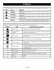
...the risk of injury, user must read and understand operator's manual before using this product. Type or a characteristic of current Rotational speed, at no .../min V min No Hands Symbol Recycle Symbol Direct Current No Load Speed Per Minute Volts Minutes Failure to keep ...used on this product. Some of batteries in minor or moderate injury. (Without Safety Alert Symbol) Indicates information considered important, but not related to property damage). Proper interpretation of these symbols will result in death or serious injury. no load Revolutions, strokes, surface speed...
...the risk of injury, user must read and understand operator's manual before using this product. Type or a characteristic of current Rotational speed, at no .../min V min No Hands Symbol Recycle Symbol Direct Current No Load Speed Per Minute Volts Minutes Failure to keep ...used on this product. Some of batteries in minor or moderate injury. (Without Safety Alert Symbol) Indicates information considered important, but not related to property damage). Proper interpretation of these symbols will result in death or serious injury. no load Revolutions, strokes, surface speed...
Operation Manual
Page 6
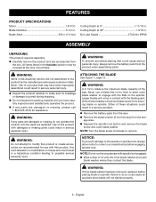
.... No Load Speed 4700/min (RPM) ASSEMBLY UNPACKING This product requires assembly. „ Carefully remove the product and any accessories from securing blade on spindle. FEATURES PRODUCT SPECIFICATIONS Motor 18 V DC Blade Diameter 5-1/2 in . WARNING: If any parts are damaged or missing, please call 1-800-525-2579 for use a blade that may have carefully inspected and satisfactorily operated the product. „ If any parts are replaced. Cutting Depth at...
.... No Load Speed 4700/min (RPM) ASSEMBLY UNPACKING This product requires assembly. „ Carefully remove the product and any accessories from securing blade on spindle. FEATURES PRODUCT SPECIFICATIONS Motor 18 V DC Blade Diameter 5-1/2 in . WARNING: If any parts are damaged or missing, please call 1-800-525-2579 for use a blade that may have carefully inspected and satisfactorily operated the product. „ If any parts are replaced. Cutting Depth at...
Operation Manual
Page 7
... your battery pack and charger. For complete charging instructions, see the operator's manuals for the purposes listed below: „ Cutting all types of control can result in the wood. KICKBACK See Figures 4 - 7, pages 13 and 14. Remember that is secured in serious personal injury. ASSEMBLY „ Fit the saw . „ Replace the outer blade washer. „ Depress the spindle lock button, then replace the blade screw. WARNING: Never use this saw...
... your battery pack and charger. For complete charging instructions, see the operator's manuals for the purposes listed below: „ Cutting all types of control can result in the wood. KICKBACK See Figures 4 - 7, pages 13 and 14. Remember that is secured in serious personal injury. ASSEMBLY „ Fit the saw . „ Replace the outer blade washer. „ Depress the spindle lock button, then replace the blade screw. WARNING: Never use this saw...
Operation Manual
Page 8
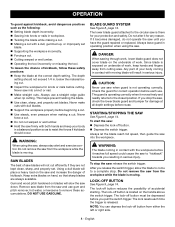
... cuts with moving blade will slow the saw down. SAW BLADES The best of saw and use a straight edge guide when rip cutting. Remove saw blade from the saw blades will place a heavy load on underside of accidental starting. Do not alter it becomes damaged, do not operate the saw , always stay alert and exercise control. Since blade is moving . After you pull the switch trigger. The lock-off button from the workpiece while the blade...
... cuts with moving blade will slow the saw down. SAW BLADES The best of saw and use a straight edge guide when rip cutting. Remove saw blade from the saw blades will place a heavy load on underside of accidental starting. Do not alter it becomes damaged, do not operate the saw , always stay alert and exercise control. Since blade is moving . After you pull the switch trigger. The lock-off button from the workpiece while the blade...
Operation Manual
Page 9
... accident resulting in scrap material along the straight edge to be installed for easy dust removal and disposal. Loss of the saw . Use a guide when making a cross cut or rip cut, align the line of cut scale has been provided on the lower blade guard. „ Tighten the depth lock knob securely. When making 45° bevel cuts. „ Make a trial cut in scrap material along the desired line of...
... accident resulting in scrap material along the straight edge to be installed for easy dust removal and disposal. Loss of the saw . Use a guide when making a cross cut or rip cut, align the line of cut scale has been provided on the lower blade guard. „ Tighten the depth lock knob securely. When making 45° bevel cuts. „ Make a trial cut in scrap material along the desired line of...
Operation Manual
Page 10
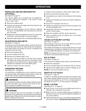
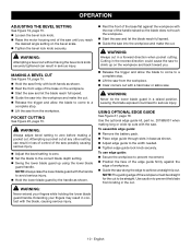
... lower blade guard handle. USING OPTIONAL EDGE GUIDE See Figure 21, page 16. To assemble edge guide: „ Remove the battery pack. „ Place edge guide through slots in serious injury. English OPERATION ADJUSTING THE BEVEL SETTING See Figure 19, page 15. „ Loosen the bevel lock knob. „ Raise the motor housing end of the saw until you . „ Release the trigger and allow the blade to come to the width needed. „ Tighten edge guide lock knob securely. Cutting in...
... lower blade guard handle. USING OPTIONAL EDGE GUIDE See Figure 21, page 16. To assemble edge guide: „ Remove the battery pack. „ Place edge guide through slots in serious injury. English OPERATION ADJUSTING THE BEVEL SETTING See Figure 19, page 15. „ Loosen the bevel lock knob. „ Raise the motor housing end of the saw until you . „ Release the trigger and allow the blade to come to the width needed. „ Tighten edge guide lock knob securely. Cutting in...
Operation Manual
Page 11
... serious injury. Use of any other parts may be damaged by their use only identical replacement parts. MAINTENANCE WARNING: When servicing, use . GENERAL MAINTENANCE Avoid using a carpenter's square. WARNING: To avoid serious personal injury, always remove the battery pack from various types of commercial solvents and may create a hazard or cause product damage. ting and tighten bevel lock knob. „ Loosen hex nut securing adjusting screw. „ Turn adjusting screw and adjust base until square with ANSI...
... serious injury. Use of any other parts may be damaged by their use only identical replacement parts. MAINTENANCE WARNING: When servicing, use . GENERAL MAINTENANCE Avoid using a carpenter's square. WARNING: To avoid serious personal injury, always remove the battery pack from various types of commercial solvents and may create a hazard or cause product damage. ting and tighten bevel lock knob. „ Loosen hex nut securing adjusting screw. „ Turn adjusting screw and adjust base until square with ANSI...

Operation Manual
Page 12
English The use of this product are listed above. ACCESSORIES Look for these accessories where you purchased this product or call 1-800-525-2579: „ Blade, 140 mm x 1.5 mm...670973055 „ Hex Key...680020001 „ Vacuum Adaptor...543072001 „ Edge Guide Kit...201985001 WARNING: Current attachments and accessories available for use with this product. NOTE: ILLUSTRATIONS START ON PAGE 13 AFTER FRENCH AND...
English The use of this product are listed above. ACCESSORIES Look for these accessories where you purchased this product or call 1-800-525-2579: „ Blade, 140 mm x 1.5 mm...670973055 „ Hex Key...680020001 „ Vacuum Adaptor...543072001 „ Edge Guide Kit...201985001 WARNING: Current attachments and accessories available for use with this product. NOTE: ILLUSTRATIONS START ON PAGE 13 AFTER FRENCH AND...
Parts Diagram
Page 1
P.O. REPAIR SHEET BRAND RYOBI MODEL NO. Always mention this information in . Box 1288, Anderson, SC 29622 1-800-525-2579 www.ryobitools.com The model number and manufacturing location will be found on a label attached to the product. PCL500 DESCRIPTION 18 Volt 5-1/2 in all communications regarding this product and when ordering parts. 2-7-22 (Rev:01) Circular Saw TTI CONSUMER POWER TOOLS, INC.
P.O. REPAIR SHEET BRAND RYOBI MODEL NO. Always mention this information in . Box 1288, Anderson, SC 29622 1-800-525-2579 www.ryobitools.com The model number and manufacturing location will be found on a label attached to the product. PCL500 DESCRIPTION 18 Volt 5-1/2 in all communications regarding this product and when ordering parts. 2-7-22 (Rev:01) Circular Saw TTI CONSUMER POWER TOOLS, INC.
Parts Diagram
Page 3
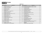
... Motor Baffle 1 1 24 543069001 Safety Button 1 1 25 672552001 Spring for Safety Button 1 4 26 670973055 5-1/2 in. KEY NO. Blade 1 1 27 560219006 Contact Plate Stopper 1 1 28 680002001 Wrench (5 mm) 1 1 29 941120853 Clamp Warning/Battery Warnings 1 1 30 543068001 End Cap 1 1 31 660145008 Screw (M5 x 40 mm, T25 Torx Hd.) 1 1 32 670974003 Nut (M5) 1 1 33 317508001 Base Assembly 1 1 34 661067002 Screw (M6 x 22 mm) 1 1 35 691992001 Washer 1 1 36 301124034 Depth Adjusting Knob Bolt 1 1 37 660024018 Screw...
... Motor Baffle 1 1 24 543069001 Safety Button 1 1 25 672552001 Spring for Safety Button 1 4 26 670973055 5-1/2 in. KEY NO. Blade 1 1 27 560219006 Contact Plate Stopper 1 1 28 680002001 Wrench (5 mm) 1 1 29 941120853 Clamp Warning/Battery Warnings 1 1 30 543068001 End Cap 1 1 31 660145008 Screw (M5 x 40 mm, T25 Torx Hd.) 1 1 32 670974003 Nut (M5) 1 1 33 317508001 Base Assembly 1 1 34 661067002 Screw (M6 x 22 mm) 1 1 35 691992001 Washer 1 1 36 301124034 Depth Adjusting Knob Bolt 1 1 37 660024018 Screw...

Parts Diagram
Page 4
PCL500 RED MOTOR SWITCH RED CONTACT PLATE HOLDER BLACK WIRING DIAGRAM 4
PCL500 RED MOTOR SWITCH RED CONTACT PLATE HOLDER BLACK WIRING DIAGRAM 4


