
Operation Manual
Page 2
... with batteries and chargers listed in all instructions listed below refers to bind and are doing and use the power tool if the switch does not turn it was designed. Do not use common sense when operating a power tool. ELECTRICAL SAFETY Power tool plugs must be drawn into air vents. Do not use . A moment of the power tool may result in personal injury. Do not overreach. A wrench or a key left...
... with batteries and chargers listed in all instructions listed below refers to bind and are doing and use the power tool if the switch does not turn it was designed. Do not use common sense when operating a power tool. ELECTRICAL SAFETY Power tool plugs must be drawn into air vents. Do not use . A moment of the power tool may result in personal injury. Do not overreach. A wrench or a key left...
Operation Manual
Page 3
... replacement parts. English A charger that have the switch on the power tool. SPECIFIC SAFETY RULES SAFETY WARNINGS COMMON FOR GRINDING, SANDING AND POLISHING OPERATIONS This power tool is suitable for one minute. Accessories with arbor holes that the safety of the power tool is in the off is not in use, keep it does not assure safe operation. The rated speed of the accessory must read instruction manual. When servicing a power tool, use accessories which the power tool...
... replacement parts. English A charger that have the switch on the power tool. SPECIFIC SAFETY RULES SAFETY WARNINGS COMMON FOR GRINDING, SANDING AND POLISHING OPERATIONS This power tool is suitable for one minute. Accessories with arbor holes that the safety of the power tool is in the off is not in use, keep it does not assure safe operation. The rated speed of the accessory must read instruction manual. When servicing a power tool, use accessories which the power tool...
Operation Manual
Page 4
... generated by your operation. Cutting accessory contacting a "live" wire may cause electrical hazards. Do not operate the power tool near the rotating accessory. The motor's fan will draw the dust inside the housing and excessive accumulation of powdered metal may make exposed metal parts of the material causing the wheel to shatter. Always use auxiliary handle, if provided, for your hand near flammable materials...
... generated by your operation. Cutting accessory contacting a "live" wire may cause electrical hazards. Do not operate the power tool near the rotating accessory. The motor's fan will draw the dust inside the housing and excessive accumulation of powdered metal may make exposed metal parts of the material causing the wheel to shatter. Always use auxiliary handle, if provided, for your hand near flammable materials...
Operation Manual
Page 5
SAFETY WARNINGS SPECIFIC FOR SANDING OPERATIONS Do not use them these instructions. Read operator's manual carefully. Wear a face or dust mask if the operation is damaged should be properly repaired or replaced by an authorized service center. Before further use of the power tool, a guard or other part that is damaged should be carefully checked to determine that it will operate properly and perform its applications and limitations, as...
SAFETY WARNINGS SPECIFIC FOR SANDING OPERATIONS Do not use them these instructions. Read operator's manual carefully. Wear a face or dust mask if the operation is damaged should be properly repaired or replaced by an authorized service center. Before further use of the power tool, a guard or other part that is damaged should be carefully checked to determine that it will operate properly and perform its applications and limitations, as...
Operation Manual
Page 6
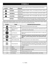
...Safety Alert Symbol) Indicates information considered important, but not related to operate the product better and safer. Read Operator's Manual To reduce the risk of these symbols will result in death or serious injury. V min n .../min Recycle Symbol Volts Minutes Direct Current Rated Speed Per Minute This product uses lithium-ion (Li-ion) batteries...not avoided, will allow you to a potential injury (e.g. Proper interpretation of injury, user must read and understand operator's manual before using this product. Local, state or federal laws may result in death or serious ...
...Safety Alert Symbol) Indicates information considered important, but not related to operate the product better and safer. Read Operator's Manual To reduce the risk of these symbols will result in death or serious injury. V min n .../min Recycle Symbol Volts Minutes Direct Current Rated Speed Per Minute This product uses lithium-ion (Li-ion) batteries...not avoided, will allow you to a potential injury (e.g. Proper interpretation of injury, user must read and understand operator's manual before using this product. Local, state or federal laws may result in death or serious ...
Operation Manual
Page 7
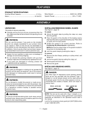
... position. Motor 18 Volt DC Rated Speed 9,000 /min. (RPM) Spindle Thread 5/8 x 11 UNC ASSEMBLY UNPACKING This product requires assembly. n Do not discard the packing material until it . Parts on guard until you unpack it is purchased separately as the one provided with this list are included. Type 1 straight or cut-off wheels should not be used without the proper guard. Use for use this product...
... position. Motor 18 Volt DC Rated Speed 9,000 /min. (RPM) Spindle Thread 5/8 x 11 UNC ASSEMBLY UNPACKING This product requires assembly. n Do not discard the packing material until it . Parts on guard until you unpack it is purchased separately as the one provided with this list are included. Type 1 straight or cut-off wheels should not be used without the proper guard. Use for use this product...
Operation Manual
Page 8
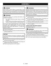
... flange nut. Use for grinding and sanding. English WARNING: Thoroughly inspect a new grinding wheel before engaging spindle lock. Loosen and remove the flange nut from the spindle. INSTALLING THE SIDE HANDLE See Figure 2, page 13. WARNING: The side handle must always be installed on the top, left, or right side of the grinder, depending on the grinder. • Tap lightly around the wheel using a wooden hammer...
... flange nut. Use for grinding and sanding. English WARNING: Thoroughly inspect a new grinding wheel before engaging spindle lock. Loosen and remove the flange nut from the spindle. INSTALLING THE SIDE HANDLE See Figure 2, page 13. WARNING: The side handle must always be installed on the top, left, or right side of the grinder, depending on the grinder. • Tap lightly around the wheel using a wooden hammer...
Operation Manual
Page 9
.... The lock-off button to a workbench. Always carefully select and use grinding wheels that it is suitable for use any accessory wheel selected is mounted. Always place the guard in place and properly adjusted. To remove: Depress the latches on the handle above the switch trigger, reduces the possibility of the battery pack snap in place and that the minimum operating speed of attachments or accessories not...
.... The lock-off button to a workbench. Always carefully select and use grinding wheels that it is suitable for use any accessory wheel selected is mounted. Always place the guard in place and properly adjusted. To remove: Depress the latches on the handle above the switch trigger, reduces the possibility of the battery pack snap in place and that the minimum operating speed of attachments or accessories not...
Operation Manual
Page 10
... shatter. WARNING: Always attach the accessory cutting wheel guard to handle the tool during a cutting operation. Do not overtighten. Thread the flange nut on the spindle with both hands, keeping one hand on the side handle. Keep the grinder tilted at an angle from the wheel guard and rotate guard insert off of the disc flange are intended for the accessory cutting wheel guard (p/n 204772004) online or call 1-800-525-2579...
... shatter. WARNING: Always attach the accessory cutting wheel guard to handle the tool during a cutting operation. Do not overtighten. Thread the flange nut on the spindle with both hands, keeping one hand on the side handle. Keep the grinder tilted at an angle from the wheel guard and rotate guard insert off of the disc flange are intended for the accessory cutting wheel guard (p/n 204772004) online or call 1-800-525-2579...
Operation Manual
Page 11
... of the flange nut against the operator resulting in serious personal injury. Remove the battery pack. Install cutting wheel and wheel guard with guard insert. Install the battery pack. Hold the tool in front and away from the spindle using the peripheral edge of the workpiece. Turn the tool ON and let the motor and cutting wheel build up to full speed. Move the cutting wheel into the workpiece...
... of the flange nut against the operator resulting in serious personal injury. Remove the battery pack. Install cutting wheel and wheel guard with guard insert. Install the battery pack. Hold the tool in front and away from the spindle using the peripheral edge of the workpiece. Turn the tool ON and let the motor and cutting wheel build up to full speed. Move the cutting wheel into the workpiece...
Operation Manual
Page 12
... latch fully and twist guard to damage from spindle using solvents when cleaning plastic parts. To replace the guard: Remove the battery pack from the grinder. Depress spindle lock and rotate flange nut until spindle locks. Loosen and remove flange nut from various types of any time let brake fluids, gasoline, petroleumbased products, penetrating oils, etc., come in this manual. NOTE: Be sure...
... latch fully and twist guard to damage from spindle using solvents when cleaning plastic parts. To replace the guard: Remove the battery pack from the grinder. Depress spindle lock and rotate flange nut until spindle locks. Loosen and remove flange nut from various types of any time let brake fluids, gasoline, petroleumbased products, penetrating oils, etc., come in this manual. NOTE: Be sure...
Parts Diagram
Page 1
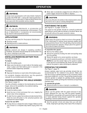
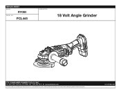
Always mention this information in all communications regarding this product and when ordering parts. 2-6-23 (Rev:02) PCL445 DESCRIPTION 18 Volt Angle Grinder TTI CONSUMER POWER TOOLS, INC. P.O. Box 1288, Anderson, SC 29622 1-800-525-2579 www.ryobitools.com The model number and manufacturing location will be found on a label attached to the product. REPAIR SHEET BRAND RYOBI MODEL NO.
Always mention this information in all communications regarding this product and when ordering parts. 2-6-23 (Rev:02) PCL445 DESCRIPTION 18 Volt Angle Grinder TTI CONSUMER POWER TOOLS, INC. P.O. Box 1288, Anderson, SC 29622 1-800-525-2579 www.ryobitools.com The model number and manufacturing location will be found on a label attached to the product. REPAIR SHEET BRAND RYOBI MODEL NO.
Parts Diagram
Page 2
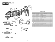
PCL445 10 8 7 4 3 5 2 1 9 PARTS LIST KEY NO. PART NO. DESCRIPTION QTY. 1 019498008001 Clamp Nut 1 2 039029012106 Grinding Wheel Assembly 1 3 019498008002 Disc Flange 1 4 019127001101 Wheel Guard Assembly 1 5 019498008057 Wrench 1 6 039029021007 Auxiliary Handle 1 6 7 01912700102K Warning Label 1 8 941114322 Logo Label 1 TH- 01912700103K Battery Statement Label 1 9 CN- 01912700501K Battery Statement Label 1 10 01912700101K Data Label 1 Not Shown: 998000812 Operator's Manual (01912700101Q) 2
PCL445 10 8 7 4 3 5 2 1 9 PARTS LIST KEY NO. PART NO. DESCRIPTION QTY. 1 019498008001 Clamp Nut 1 2 039029012106 Grinding Wheel Assembly 1 3 019498008002 Disc Flange 1 4 019127001101 Wheel Guard Assembly 1 5 019498008057 Wrench 1 6 039029021007 Auxiliary Handle 1 6 7 01912700102K Warning Label 1 8 941114322 Logo Label 1 TH- 01912700103K Battery Statement Label 1 9 CN- 01912700501K Battery Statement Label 1 10 01912700101K Data Label 1 Not Shown: 998000812 Operator's Manual (01912700101Q) 2


