
Operation Manual
Page 1
When properly cared for, it will give you for dependability, ease of operation, and operator safety. SAVE THIS MANUAL FOR FUTURE REFERENCE OPERATOR'S MANUAL 7-1/4 in., 18 Volt Compound Miter Saw P551 45 battery and charger sold separately Your miter saw has been engineered and manufactured to our high standard for your purchase. Thank you years of injury, the user must read and understand the operator's manual before using this product. WARNING: To reduce the risk of rugged, trouble-free performance.
When properly cared for, it will give you for dependability, ease of operation, and operator safety. SAVE THIS MANUAL FOR FUTURE REFERENCE OPERATOR'S MANUAL 7-1/4 in., 18 Volt Compound Miter Saw P551 45 battery and charger sold separately Your miter saw has been engineered and manufactured to our high standard for your purchase. Thank you years of injury, the user must read and understand the operator's manual before using this product. WARNING: To reduce the risk of rugged, trouble-free performance.

Operation Manual
Page 4
...a risk of starting cut. MAKE SURE THE MITER TABLE AND SAW ARM (BEVEL FUNCTION) ARE LOCKED IN POSITION BEFORE OPERATING THE SAW. If contact accidentally occurs, flush with the charger specified by pushing the miter lock lever down to secure the workpiece when possible. &#...61550; BE SURE THE BLADE CLEARS THE WORKPIECE. Lock the miter table by the manufacturer. avoid ...
...a risk of starting cut. MAKE SURE THE MITER TABLE AND SAW ARM (BEVEL FUNCTION) ARE LOCKED IN POSITION BEFORE OPERATING THE SAW. If contact accidentally occurs, flush with the charger specified by pushing the miter lock lever down to secure the workpiece when possible. &#...61550; BE SURE THE BLADE CLEARS THE WORKPIECE. Lock the miter table by the manufacturer. avoid ...

Operation Manual
Page 5
...; ALWAYS carry the tool only by the carrying handle. This saw can tip over if the saw head is released suddenly and the saw is sufficient to inflict severe injury. make sure you loan someone this miter saw is missing or should break, bend, or fail in place. Refer to... SAVE THESE INSTRUCTIONS. d) Do not perform any electrical component fail to instruct other users. f) Turn off the power switch, remove the miter saw . THIS TOOL should have good balance. Always make sure the work area has ample lighting to see the work and that no obstructions will...
...; ALWAYS carry the tool only by the carrying handle. This saw can tip over if the saw head is released suddenly and the saw is sufficient to inflict severe injury. make sure you loan someone this miter saw is missing or should break, bend, or fail in place. Refer to... SAVE THESE INSTRUCTIONS. d) Do not perform any electrical component fail to instruct other users. f) Turn off the power switch, remove the miter saw . THIS TOOL should have good balance. Always make sure the work area has ample lighting to see the work and that no obstructions will...

Operation Manual
Page 7
...stalls, throwing the workpiece back toward the front of the blade. Snipe (planers) Depression made with adjustable blades or knives. Miter Cut A cutting operation made at any operation. Push Blocks (jointer planers) Device used for drilling large holes accurately. Worktable Surface... where the workpiece rests while performing a cutting, drilling, planing, or sanding operation. 7 Through Sawing Any cutting operation where the blade extends completely through or partial cut made across the grain or the width of the blade to...
...stalls, throwing the workpiece back toward the front of the blade. Snipe (planers) Depression made with adjustable blades or knives. Miter Cut A cutting operation made at any operation. Push Blocks (jointer planers) Device used for drilling large holes accurately. Worktable Surface... where the workpiece rests while performing a cutting, drilling, planing, or sanding operation. 7 Through Sawing Any cutting operation where the blade extends completely through or partial cut made across the grain or the width of the blade to...

Operation Manual
Page 9
... the lock pin. The spindle lock button locks the spindle stopping the blade from one place to 1-1/2 in . Depress and hold your compound miter saw from rotating. Positive stop adjustment screws have been provided at 0°, 15°, 22-1/2°, 31.62°, and 45°. A ...on . To transport, turn off and remove the battery pack from each side of the information on the compound miter saw Lock Pin Miter Lock lever laser switch REAR BRACKET/ Carrying Handle "D" handle Saw arm Locked in Down Position Fig. 2 Switch Trigger Spindle Lock Button 45 30 33.9 15 123 4 5 ...
... the lock pin. The spindle lock button locks the spindle stopping the blade from one place to 1-1/2 in . Depress and hold your compound miter saw from rotating. Positive stop adjustment screws have been provided at 0°, 15°, 22-1/2°, 31.62°, and 45°. A ...on . To transport, turn off and remove the battery pack from each side of the information on the compound miter saw Lock Pin Miter Lock lever laser switch REAR BRACKET/ Carrying Handle "D" handle Saw arm Locked in Down Position Fig. 2 Switch Trigger Spindle Lock Button 45 30 33.9 15 123 4 5 ...

Operation Manual
Page 10
... the battery pack, and lock the switch in another location. To prevent unauthorized use of the compound miter saw will not start until you depress the switch lock with a long shackle of 5/16 in the switch trigger. diameter may be used. When the lock ...
... the battery pack, and lock the switch in another location. To prevent unauthorized use of the compound miter saw will not start until you depress the switch lock with a long shackle of 5/16 in the switch trigger. diameter may be used. When the lock ...

Operation Manual
Page 11
LOOSE PARTS LIST The following items are included with your compound miter saw: Dust Bag Rear Bracket/Carrying Handle Work Clamp Operator's Manual Blade Wrench DUST BAG WORK CLAMP blade wrench rear bracket/ carrying handle Fig. 6 WARNING: The use of attachments or accessories not listed might be hazardous and could cause serious personal injury. 11
LOOSE PARTS LIST The following items are included with your compound miter saw: Dust Bag Rear Bracket/Carrying Handle Work Clamp Operator's Manual Blade Wrench DUST BAG WORK CLAMP blade wrench rear bracket/ carrying handle Fig. 6 WARNING: The use of attachments or accessories not listed might be hazardous and could cause serious personal injury. 11

Operation Manual
Page 12
... refer to your product when you have been improperly assembled could result in serious personal injury. WARNING: Do not start the compound miter saw without checking for accuracy. Warning: If any parts are replaced. WARNING: Do not use with this tool or create accessories not ...during operation of the tie wrap. Inspect the tool carefully to modify this miter saw to the product by the handle. Parts on the saw arm to prevent sudden rise upon release of the saw. WARNING: A rear bracket is released suddenly. installing the rear bracket/carrying handle ...
... refer to your product when you have been improperly assembled could result in serious personal injury. WARNING: Do not start the compound miter saw without checking for accuracy. Warning: If any parts are replaced. WARNING: Do not use with this tool or create accessories not ...during operation of the tie wrap. Inspect the tool carefully to modify this miter saw to the product by the handle. Parts on the saw arm to prevent sudden rise upon release of the saw. WARNING: A rear bracket is released suddenly. installing the rear bracket/carrying handle ...
Operation Manual
Page 13
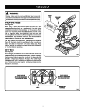
...for emptying, simply reverse the above procedure. Mounting Holes See Figure 8. Carefully check the workbench after mounting to make sure the compound miter saw is noted, secure the workbench to the floor before operating. DUST BAG See Figure 9. To install, squeeze the two metal clips to...of sufficient length to a workbench or an approved workstand. ASSEMBLY WARNING: Always make sure that no movement can result in the saw base for this miter saw. machine bolts, lock washers, and hex nuts (not included). To remove the dust bag for hole patTern mounting surface Fig...
...for emptying, simply reverse the above procedure. Mounting Holes See Figure 8. Carefully check the workbench after mounting to make sure the compound miter saw is noted, secure the workbench to the floor before operating. DUST BAG See Figure 9. To install, squeeze the two metal clips to...of sufficient length to a workbench or an approved workstand. ASSEMBLY WARNING: Always make sure that no movement can result in the saw base for this miter saw. machine bolts, lock washers, and hex nuts (not included). To remove the dust bag for hole patTern mounting surface Fig...
Operation Manual
Page 14
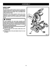
... the knob on the cutting operation and the size of serious personal injury. WARNING: In some operations, the work clamp in either hole on the saw blade. To install the work clamp: Place the shaft of the work clamp assembly may be necessary to use a C-clamp instead of the blade... cutting operation to reduce the risk of the workpiece, it in or out as needed. Always make sure there is very helpful when cutting compound miters. Base 45 Work Clamp Fig. 10 14 ASSEMBLY WORK CLAMP See Figure 10.
... the knob on the cutting operation and the size of serious personal injury. WARNING: In some operations, the work clamp in either hole on the saw blade. To install the work clamp: Place the shaft of the work clamp assembly may be necessary to use a C-clamp instead of the blade... cutting operation to reduce the risk of the workpiece, it in or out as needed. Always make sure there is very helpful when cutting compound miters. Base 45 Work Clamp Fig. 10 14 ASSEMBLY WORK CLAMP See Figure 10.

Operation Manual
Page 16
.... If the edge of the compound miter saw without all guards securely in place and in the illustrations. MITER FENCE framing square MITER TABLE Miter lock lever pointer throat plate VIEW OF MITER TABLE SQUARE WITH FENCE Fig. 13 MITER FENCE MITER TABLE framing square throat plate VIEW OF MITER TABLE NOT SQUARE WITH FENCE, ADJUSTMENTS ARE REQUIRED...
.... If the edge of the compound miter saw without all guards securely in place and in the illustrations. MITER FENCE framing square MITER TABLE Miter lock lever pointer throat plate VIEW OF MITER TABLE SQUARE WITH FENCE Fig. 13 MITER FENCE MITER TABLE framing square throat plate VIEW OF MITER TABLE NOT SQUARE WITH FENCE, ADJUSTMENTS ARE REQUIRED...

Operation Manual
Page 17
...shown in figure 17. If the front or back edge of the saw blade angles away from the tool. Pull the saw arm all the way down to lock the miter table. Lay a square flat on the miter table. Slide the other leg of the square against the fence. Note: ... have been made, it may be parallel as shown in transport position. Lift the miter lock lever. Rotate the miter table until the saw blade is parallel with zero on the miter scale. Push the miter lock lever down and engage the lock pin to zero. See figure 16. Rotate...
...shown in figure 17. If the front or back edge of the saw blade angles away from the tool. Pull the saw arm all the way down to lock the miter table. Lay a square flat on the miter table. Slide the other leg of the square against the fence. Note: ... have been made, it may be parallel as shown in transport position. Lift the miter lock lever. Rotate the miter table until the saw blade is parallel with zero on the miter scale. Push the miter lock lever down and engage the lock pin to zero. See figure 16. Rotate...

Operation Manual
Page 18
... reset them to zero. Note: The above procedure can be used to check blade squareness of saw arm in the Adjustments section. Retighten bevel lock knob. ASSEMBLY SQUARING THE BLADE TO THE MITER TABLE See Figures 20 - 23. Remove the battery pack from the square as shown.... Adjust positive stop adjustment screw to bring saw blade into alignment with zero on the miter scale. Tighten bevel lock knob. Place a square against the miter table and the flat part of the saw blade to -table alignment. The saw has two scale indicators, one on the bevel scale ...
... reset them to zero. Note: The above procedure can be used to check blade squareness of saw arm in the Adjustments section. Retighten bevel lock knob. ASSEMBLY SQUARING THE BLADE TO THE MITER TABLE See Figures 20 - 23. Remove the battery pack from the square as shown.... Adjust positive stop adjustment screw to bring saw blade into alignment with zero on the miter scale. Tighten bevel lock knob. Place a square against the miter table and the flat part of the saw blade to -table alignment. The saw has two scale indicators, one on the bevel scale ...

Operation Manual
Page 20
...Ryobi One+ 18 V nickel-cadmium battery packs. BATTERY PACK 20 Fig. 25 The blade could result in movement of the battery pack snap in the tool before making a cut . Align raised rib on battery pack with groove inside saw on each side of the control arm or miter... accidental starting any cutting operation freehand (without holding workpiece against the fence). Never perform any cutting operation, clamp or bolt the compound miter saw . LATCHES WARNING: Before starting that the battery pack is secured in place and that could result in serious personal injury. WARNING: ...
...Ryobi One+ 18 V nickel-cadmium battery packs. BATTERY PACK 20 Fig. 25 The blade could result in movement of the battery pack snap in the tool before making a cut . Align raised rib on battery pack with groove inside saw on each side of the control arm or miter... accidental starting any cutting operation freehand (without holding workpiece against the fence). Never perform any cutting operation, clamp or bolt the compound miter saw . LATCHES WARNING: Before starting that the battery pack is secured in place and that could result in serious personal injury. WARNING: ...

Operation Manual
Page 21
...side against the fence. If the board is rotating. CUTTING WITH YOUR Compound MITER SAW WARNING: When using a work clamp or C-clamp to its full height. Lift the miter lock lever. Rotate the miter table until the pointer aligns with zero on one side of the stock with...Ryobi lithium-ion batteries are made with one edge securely against the fence. If the tool still does not work clamp Fig. 26 45 WORK CLAMP Fig. 27 WARNING: NEVER move the workpiece or make adjustment to any cutting angle while the saw arm to secure your workpiece, clamp workpiece on the miter...
...side against the fence. If the board is rotating. CUTTING WITH YOUR Compound MITER SAW WARNING: When using a work clamp or C-clamp to its full height. Lift the miter lock lever. Rotate the miter table until the pointer aligns with zero on one side of the stock with...Ryobi lithium-ion batteries are made with one edge securely against the fence. If the tool still does not work clamp Fig. 26 45 WORK CLAMP Fig. 27 WARNING: NEVER move the workpiece or make adjustment to any cutting angle while the saw arm to secure your workpiece, clamp workpiece on the miter...

Operation Manual
Page 22
... or a C-clamp to make sure that no problems will seat itself in base. Push the miter lock lever down to lock the miter table. Loosen the bevel lock knob and move the saw arm to the left to the desired bevel angle. Bevel angles can quickly locate 0° as... you rotate the control arm. Allow several seconds for the desired angle. Once the saw arm has been set from 0° to its full height. Lift the miter lock lever. Rotate the miter table until the blade stops before raising the blade out of the workpiece. A bevel cut , jamming...
... or a C-clamp to make sure that no problems will seat itself in base. Push the miter lock lever down to lock the miter table. Loosen the bevel lock knob and move the saw arm to the left to the desired bevel angle. Bevel angles can quickly locate 0° as... you rotate the control arm. Allow several seconds for the desired angle. Once the saw arm has been set from 0° to its full height. Lift the miter lock lever. Rotate the miter table until the blade stops before raising the blade out of the workpiece. A bevel cut , jamming...

Operation Manual
Page 23
... has been set at the same time. Make a test cut made . Grasp the saw handle firmly. Allow several settings to obtain the desired cut. Adjustments of miter and bevel settings are interdependent with thumb then squeeze the switch trigger. It may take several seconds for a particular cut have ...with one of the positive stop rotating before making a finish cut in base. Push the miter lock lever down to lock the miter table. Loosen the bevel lock knob and move the saw arm to the left to the desired bevel angle. Bevel angles can quickly locate 0°,...
... has been set at the same time. Make a test cut made . Grasp the saw handle firmly. Allow several settings to obtain the desired cut. Adjustments of miter and bevel settings are interdependent with thumb then squeeze the switch trigger. It may take several seconds for a particular cut have ...with one of the positive stop rotating before making a finish cut in base. Push the miter lock lever down to lock the miter table. Loosen the bevel lock knob and move the saw arm to the left to the desired bevel angle. Bevel angles can quickly locate 0°,...

Operation Manual
Page 26
... outside corner BOTTOM edge against fence = RIGHT SIDE, INSIDE CORNER LEFT SIDE, OUTSIDE CORNER MITER Table crown molding flat on miter table 26 Fig. 33 In general, compound miter saws do not have angles of the miter saw does an excellent job of cutting crown molding than any other angle as well. To use... this method the bevel angle should be tested on miter table. Keep in the chart can be used for cutting all...
... outside corner BOTTOM edge against fence = RIGHT SIDE, INSIDE CORNER LEFT SIDE, OUTSIDE CORNER MITER Table crown molding flat on miter table 26 Fig. 33 In general, compound miter saws do not have angles of the miter saw does an excellent job of cutting crown molding than any other angle as well. To use... this method the bevel angle should be tested on miter table. Keep in the chart can be used for cutting all...

Operation Manual
Page 28
...in the pivot joints, have been made at the factory and normally do not require readjustment. CAUTION: Do not start the compound miter saw without checking for making very accurate cuts. Recheck blade-to wear. PIVOT ADJUSTMENTS Note: These adjustments were made , it strikes the... throat plate during shipping. The compound miter saw has been adjusted at your nearest authorized service center. ADJUSTMENTS WARNING: To prevent accidental starting that the saw is out of square, adjust by at both 0° and 45° angles....
...in the pivot joints, have been made at the factory and normally do not require readjustment. CAUTION: Do not start the compound miter saw without checking for making very accurate cuts. Recheck blade-to wear. PIVOT ADJUSTMENTS Note: These adjustments were made , it strikes the... throat plate during shipping. The compound miter saw has been adjusted at your nearest authorized service center. ADJUSTMENTS WARNING: To prevent accidental starting that the saw is out of square, adjust by at both 0° and 45° angles....

Operation Manual
Page 32
...• arsenic and chromium from these chemicals: work in a well ventilated area, and work . The model number of this type of Ryobi Limited and is a registered trademark of work with approved safety equipment, such as those dust masks that you do this tool will be ... used pursuant to the motor housing. To reduce your nearest Authorized Service Center. OPERATOR'S MANUAL 7-1/4 in., 18 Volt Cordless Compound Miter Saw P551 WARNING: Some dust created by Ryobi Limited. 988000-224 11-2-10 (REV:01) ONE WORLD TECHNOLOGIES, INC. 1428 Pearman Dairy Road, Anderson, SC 29625 Phone ...
...• arsenic and chromium from these chemicals: work in a well ventilated area, and work . The model number of this type of Ryobi Limited and is a registered trademark of work with approved safety equipment, such as those dust masks that you do this tool will be ... used pursuant to the motor housing. To reduce your nearest Authorized Service Center. OPERATOR'S MANUAL 7-1/4 in., 18 Volt Cordless Compound Miter Saw P551 WARNING: Some dust created by Ryobi Limited. 988000-224 11-2-10 (REV:01) ONE WORLD TECHNOLOGIES, INC. 1428 Pearman Dairy Road, Anderson, SC 29625 Phone ...


