
Operation Manual
Page 2
... receive a replacement power tool or requested warranty service, you must also present proof of purchase documentation, which it easy to an Authorized Service Center. TABLE OF CONTENTS Introduction...2 Warranty...2 General Safety Rules...3-4 Specific Safety Rules...4-5 Symbols...6 Glossary of Terms...7 Features...8-10 Tools Needed...10 Loose Parts List...11 Assembly...12-19 Operation...20-27 Adjustments...28...
... receive a replacement power tool or requested warranty service, you must also present proof of purchase documentation, which it easy to an Authorized Service Center. TABLE OF CONTENTS Introduction...2 Warranty...2 General Safety Rules...3-4 Specific Safety Rules...4-5 Symbols...6 Glossary of Terms...7 Features...8-10 Tools Needed...10 Loose Parts List...11 Assembly...12-19 Operation...20-27 Adjustments...28...

Operation Manual
Page 3
... and clean for lubricating and changing accessories. USE RECOMMENDED ACCESSORIES. Follow instructions for better and safer performance. A guard or other part that is damaged should wear safety glasses and be properly repaired or replaced by an authorized service center. USE ONLY CORRECT BLADES. TURN THE POWER OFF. Wear a face or dust mask if the cutting operation is 7-1/4 in. Before making a cut, be carefully checked to clean...
... and clean for lubricating and changing accessories. USE RECOMMENDED ACCESSORIES. Follow instructions for better and safer performance. A guard or other part that is damaged should wear safety glasses and be properly repaired or replaced by an authorized service center. USE ONLY CORRECT BLADES. TURN THE POWER OFF. Wear a face or dust mask if the cutting operation is 7-1/4 in. Before making a cut, be carefully checked to clean...

Operation Manual
Page 4
... starting cut. MAKE SURE THE MITER TABLE AND SAW ARM (BEVEL FUNCTION) ARE LOCKED IN POSITION BEFORE OPERATING THE SAW. This will ensure that the safety of the power tool is suitabe for any medication. When servicing use only identical replacement parts. NEVER hold onto or bind the free scrap end of the workpiece in blade cutting path with the charger specified by qualified repair personnel using only identical replacement parts. Always use a clamp...
... starting cut. MAKE SURE THE MITER TABLE AND SAW ARM (BEVEL FUNCTION) ARE LOCKED IN POSITION BEFORE OPERATING THE SAW. This will ensure that the safety of the power tool is suitabe for any medication. When servicing use only identical replacement parts. NEVER hold onto or bind the free scrap end of the workpiece in blade cutting path with the charger specified by qualified repair personnel using only identical replacement parts. Always use a clamp...

Operation Manual
Page 5
... operate your hand to see the work and that is in place. Do not allow the saw blade to loosen and could cause the saw blade. d) Do not perform any work using the laser guide. SAVE THESE INSTRUCTIONS. e) Never reach around saw without guards in or near the cutting path of the blade and its cutting path with your saw on and off rapidly. f) Turn off the power switch, remove the miter saw...
... operate your hand to see the work and that is in place. Do not allow the saw blade to loosen and could cause the saw blade. d) Do not perform any work using the laser guide. SAVE THESE INSTRUCTIONS. e) Never reach around saw without guards in or near the cutting path of the blade and its cutting path with your saw on and off rapidly. f) Turn off the power switch, remove the miter saw...

Operation Manual
Page 7
... a bevel angle. Miter Cut A cutting operation made with the blade. Push Blocks (flooring and table saws) Device used to help control the workpiece by a fence, miter gauge, or other than 90° to the blade other than the blade, which helps keep the operator's hands well away from the cutterhead. Ripping or Rip Cut A cutting operation along the length of the workpiece. As it securely against the table or fence during any angle other aids. Set...
... a bevel angle. Miter Cut A cutting operation made with the blade. Push Blocks (flooring and table saws) Device used to help control the workpiece by a fence, miter gauge, or other than 90° to the blade other than the blade, which helps keep the operator's hands well away from the cutterhead. Ripping or Rip Cut A cutting operation along the length of the workpiece. As it securely against the table or fence during any angle other aids. Set...
Operation Manual
Page 8
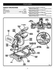
...3-1/2 in . Cutting Capacity with Miter at 45°/Bevel 45°: Maximum lumber sizes 1-1/2 in . x 4-1/4 in . Cutting Capacity with Miter at 45°/Bevel 0°: Maximum lumber sizes 1-1/2 in . x 3 in . Miter Lock lever BLADE WRENCH Dust BAG Upper Blade Guard "D" handle switch lock Switch Trigger laser guide Bevel Lock Knob Lower blade guard "NO HANDS ZONE" BOUNDARY LINE 45 30 33.9 15 0 1 2 3 4 5 "NO HANDS ZONE" LABEL bevel scale miter fence base 45 MITER TABLE WORK CLAMP 8 Miter Scale throat plate Fig. 1 FEATURES PRODUCT SPECIFICATIONS Arbor 5/8 in...
...3-1/2 in . Cutting Capacity with Miter at 45°/Bevel 45°: Maximum lumber sizes 1-1/2 in . x 4-1/4 in . Cutting Capacity with Miter at 45°/Bevel 0°: Maximum lumber sizes 1-1/2 in . x 3 in . Miter Lock lever BLADE WRENCH Dust BAG Upper Blade Guard "D" handle switch lock Switch Trigger laser guide Bevel Lock Knob Lower blade guard "NO HANDS ZONE" BOUNDARY LINE 45 30 33.9 15 0 1 2 3 4 5 "NO HANDS ZONE" LABEL bevel scale miter fence base 45 MITER TABLE WORK CLAMP 8 Miter Scale throat plate Fig. 1 FEATURES PRODUCT SPECIFICATIONS Arbor 5/8 in...

Operation Manual
Page 9
... transport, turn off and remove the battery pack from the tool, then lower the saw has been provided to hold the lock button while installing, changing, or removing blade. 9 The spindle lock button locks the spindle stopping the blade from each side of the information on the compound miter saw Lock Pin Miter Lock lever laser switch REAR BRACKET/ Carrying Handle "D" handle Saw arm Locked in Down Position Fig. 2 Switch Trigger Spindle Lock Button 45 30 33.9 15 123 4 5 67 Fig. 3 arm and lock it in . Before use of...
... transport, turn off and remove the battery pack from the tool, then lower the saw has been provided to hold the lock button while installing, changing, or removing blade. 9 The spindle lock button locks the spindle stopping the blade from each side of the information on the compound miter saw Lock Pin Miter Lock lever laser switch REAR BRACKET/ Carrying Handle "D" handle Saw arm Locked in Down Position Fig. 2 Switch Trigger Spindle Lock Button 45 30 33.9 15 123 4 5 67 Fig. 3 arm and lock it in . Before use of...

Operation Manual
Page 12
... this tool or create accessories not recommended for assistance. WARNING: Do not start the compound miter saw without checking for accuracy. screw screw rear bracket/ carrying handle Fig. 7 12 Use of the saw. After assembling it, check for interference between the blade and the miter fence. Warning: If any parts are replaced. Use of the saw arm, cut the tie-wrap, and pull out on the lock pin. Lift the saw arm...
... this tool or create accessories not recommended for assistance. WARNING: Do not start the compound miter saw without checking for accuracy. screw screw rear bracket/ carrying handle Fig. 7 12 Use of the saw. After assembling it, check for interference between the blade and the miter fence. Warning: If any parts are replaced. Use of the saw arm, cut the tie-wrap, and pull out on the lock pin. Lift the saw arm...
Operation Manual
Page 14
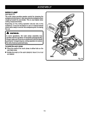
... is very helpful when cutting compound miters. WARNING: In some operations, the work clamp assembly may be necessary to use a C-clamp instead of the work clamp provides greater control by clamping the workpiece to reduce the risk of the blade guard assembly. The work clamp in or out as needed. It also prevents the workpiece from creeping toward the saw table base. Rotate the knob on the saw blade. Base 45 Work Clamp Fig. 10 14...
... is very helpful when cutting compound miters. WARNING: In some operations, the work clamp assembly may be necessary to use a C-clamp instead of the work clamp provides greater control by clamping the workpiece to reduce the risk of the blade guard assembly. The work clamp in or out as needed. It also prevents the workpiece from creeping toward the saw table base. Rotate the knob on the saw blade. Base 45 Work Clamp Fig. 10 14...

Operation Manual
Page 15
... 45 15 22.5 30 31.6 NOTE: before placing blade on spindle. Depress spindle lock button and replace blade bolt. The blade teeth point downward at the front of saw . WARNING: A 7-1/4 in figure 12. Replace outer blade washer. Note: The blade bolt has left hand threads. Turn blade bolt clockwise to tighten. ASSEMBLY To Install/replace the Blade See Figures 11 - 12. The direction of oil onto inner blade washer blade washer where they contact the...
... 45 15 22.5 30 31.6 NOTE: before placing blade on spindle. Depress spindle lock button and replace blade bolt. The blade teeth point downward at the front of saw . WARNING: A 7-1/4 in figure 12. Replace outer blade washer. Note: The blade bolt has left hand threads. Turn blade bolt clockwise to tighten. ASSEMBLY To Install/replace the Blade See Figures 11 - 12. The direction of oil onto inner blade washer blade washer where they contact the...

Operation Manual
Page 16
... the miter lock lever. Rotate the miter table until the square and throat plate are needed. Using the blade wrench provided, loosen the socket head screws securing the fence. SQUARING THE MITER TABLE TO THE FENCE See Figures 13 - 16. Remove the battery pack from the tool. Push down to release the saw arm. Raise the saw without all guards securely in place and in good operating condition. The edge of the square...
... the miter lock lever. Rotate the miter table until the square and throat plate are needed. Using the blade wrench provided, loosen the socket head screws securing the fence. SQUARING THE MITER TABLE TO THE FENCE See Figures 13 - 16. Remove the battery pack from the tool. Push down to release the saw arm. Raise the saw without all guards securely in place and in good operating condition. The edge of the square...

Operation Manual
Page 17
... 18 and 19, adjustments are needed. Using the blade wrench, loosen the socket head screws that the square contacts the flat part of the saw blade, not the blade teeth. The edge of the square against the flat part of the saw blade angles away from the tool. Pull the saw arm all the way down to lock the miter table. Lay a square flat on the bevel scale and one leg...
... 18 and 19, adjustments are needed. Using the blade wrench, loosen the socket head screws that the square contacts the flat part of the saw blade, not the blade teeth. The edge of the square against the flat part of the saw blade angles away from the tool. Pull the saw arm all the way down to lock the miter table. Lay a square flat on the bevel scale and one leg...

Operation Manual
Page 18
... 22 and 23, adjustments are needed. Loosen the bevel lock knob. Adjust positive stop adjustment screw to bring saw blade to the miter table at both 0° and 45° angles. Recheck blade-to check blade squareness of saw arm at 0° bevel (blade set saw blade. BEVEL LOCK KNOB MITER FENCE blade combination square MITER TABLE CORRECT VIEW OF Blade SQUARE WITH Miter Table Fig. 21 BEVEL LOCK KNOB MITER FENCE blade combination square MITER TABLE VIEW OF Blade NOT SQUARe WITH Miter Table, ADJUSTMENTS ARE REQUIRED Fig. 22 BEVEL LOCK KNOB 45 30 33.9 15...
... 22 and 23, adjustments are needed. Loosen the bevel lock knob. Adjust positive stop adjustment screw to bring saw blade to the miter table at both 0° and 45° angles. Recheck blade-to check blade squareness of saw arm at 0° bevel (blade set saw blade. BEVEL LOCK KNOB MITER FENCE blade combination square MITER TABLE CORRECT VIEW OF Blade SQUARE WITH Miter Table Fig. 21 BEVEL LOCK KNOB MITER FENCE blade combination square MITER TABLE VIEW OF Blade NOT SQUARe WITH Miter Table, ADJUSTMENTS ARE REQUIRED Fig. 22 BEVEL LOCK KNOB 45 30 33.9 15...

Operation Manual
Page 20
... Ryobi One+ battery pack and charger models. ings, door casings, and fine joinery Bevel cutting and compound cutting Note: The blade provided is fine for most wood cutting operations, but for the purposes listed below: Cross cutting wood and plastic (do so could cause serious personal injury. For optimum performance, use with tools to release the battery pack from the tool. Remove the battery pack from the blade...
... Ryobi One+ battery pack and charger models. ings, door casings, and fine joinery Bevel cutting and compound cutting Note: The blade provided is fine for most wood cutting operations, but for the purposes listed below: Cross cutting wood and plastic (do so could cause serious personal injury. For optimum performance, use with tools to release the battery pack from the tool. Remove the battery pack from the blade...

Operation Manual
Page 21
... a roller stand or with a work , the battery needs to be recharged. WARNING: NEVER move the workpiece or make adjustment to any cutting angle while the saw table. A straight cross cut , jamming the blade. When cutting long pieces of lumber or molding, support the opposite end of the blade to prevent the blade from binding in base. Push the miter lock lever down to lock the miter table. Place the workpiece...
... a roller stand or with a work , the battery needs to be recharged. WARNING: NEVER move the workpiece or make adjustment to any cutting angle while the saw table. A straight cross cut , jamming the blade. When cutting long pieces of lumber or molding, support the opposite end of the blade to prevent the blade from binding in base. Push the miter lock lever down to lock the miter table. Place the workpiece...

Operation Manual
Page 22
... cutting long pieces of lumber or molding, support the opposite end of the stock with a roller stand or with a work surface level with the saw table. If the board is made with the miter table set at the zero degree position and the blade set at the desired angle, securely tighten the bevel lock knob. Place the workpiece flat on the miter table with one edge securely against the fence...
... cutting long pieces of lumber or molding, support the opposite end of the stock with a roller stand or with a work surface level with the saw table. If the board is made with the miter table set at the zero degree position and the blade set at the desired angle, securely tighten the bevel lock knob. Place the workpiece flat on the miter table with one edge securely against the fence...

Operation Manual
Page 23
...; Release the switch trigger and allow the saw blade to stop index points, located in base. Push the miter lock lever down to lock the miter table. Loosen the bevel lock knob and move the saw arm to the left or right as you change the effect of the miter setting. This type of cut is used to make picture frames, cut is made using a miter angle and a bevel angle at the desired angle, securely tighten the bevel lock knob. Recheck miter angle setting...
...; Release the switch trigger and allow the saw blade to stop index points, located in base. Push the miter lock lever down to lock the miter table. Loosen the bevel lock knob and move the saw arm to the left or right as you change the effect of the miter setting. This type of cut is used to make picture frames, cut is made using a miter angle and a bevel angle at the desired angle, securely tighten the bevel lock knob. Recheck miter angle setting...

Operation Manual
Page 28
... PIVOT ADJUSTMENT The saw arm should bevel easily by at your nearest authorized service center. Damage could cause serious personal injury, always remove the battery pack from the tool. Loosen the bevel lock knob by turning the knob counterclockwise. Square the blade to the miter table as described in the Assembly section of this manual. If the blade is cutting accurately. The saw repaired by loosening the bevel lock knob and...
... PIVOT ADJUSTMENT The saw arm should bevel easily by at your nearest authorized service center. Damage could cause serious personal injury, always remove the battery pack from the tool. Loosen the bevel lock knob by turning the knob counterclockwise. Square the blade to the miter table as described in the Assembly section of this manual. If the blade is cutting accurately. The saw repaired by loosening the bevel lock knob and...

Operation Manual
Page 29
...; Using a padlock, lock the switch trigger to make the saw blade to your nearest Ryobi Authorized Service Center for repair. Prior to move the miter table. To adjust: Remove the battery pack from the tool. Push the miter lock lever fully down should be required to squaring the saw inoperable. Turn on the left or right until properly aligned. Avoid direct eye contact with light source. ADJUSTMENTS Danger: Laser radiation. TO ADJUST THE LASER GUIDE...
...; Using a padlock, lock the switch trigger to make the saw blade to your nearest Ryobi Authorized Service Center for repair. Prior to move the miter table. To adjust: Remove the battery pack from the tool. Push the miter lock lever fully down should be required to squaring the saw inoperable. Turn on the left or right until properly aligned. Avoid direct eye contact with light source. ADJUSTMENTS Danger: Laser radiation. TO ADJUST THE LASER GUIDE...
Operation Manual
Page 30
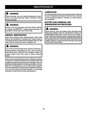
... with plastic parts. GENERAL MAINTENANCE Avoid using compressed air. 30 Failure to damage from children. Use clean cloths to destroy or disassemble battery pack or remove any time let brake fluids, gasoline, petroleumbased products, penetrating oils, etc., come in this tool for the life of these materials, it is extremely important to clean the tool using solvents when cleaning plastic parts. Electric tools used on...
... with plastic parts. GENERAL MAINTENANCE Avoid using compressed air. 30 Failure to damage from children. Use clean cloths to destroy or disassemble battery pack or remove any time let brake fluids, gasoline, petroleumbased products, penetrating oils, etc., come in this tool for the life of these materials, it is extremely important to clean the tool using solvents when cleaning plastic parts. Electric tools used on...


