
Operation Manual
Page 2
... earthed (grounded) power tools. Always wear eye protection. Ensure the switch is an increased risk of dust collection can reduce dust-related hazards. Do not let familiarity gained from heat, oil, sharp edges or moving parts. Use of electric shock if your mainsoperated (corded) power tool or battery-operated (cordless) power tool. Stable footing on . Cluttered or dark areas invite accidents. Do not operate power tools in explosive atmospheres...
... earthed (grounded) power tools. Always wear eye protection. Ensure the switch is an increased risk of dust collection can reduce dust-related hazards. Do not let familiarity gained from heat, oil, sharp edges or moving parts. Use of electric shock if your mainsoperated (corded) power tool or battery-operated (cordless) power tool. Stable footing on . Cluttered or dark areas invite accidents. Do not operate power tools in explosive atmospheres...
Operation Manual
Page 3
... ejected from oil and grease. Damaged or modified batteries may be performed by a qualified repair person using only identical replacement parts. Service of injury. Do not expose a battery pack or tool to control. Use the power tool, accessories and tool bits etc. Charging improperly or at the rate for operations different from one type of battery pack may cause explosion. Follow all charging instructions and do...
... ejected from oil and grease. Damaged or modified batteries may be performed by a qualified repair person using only identical replacement parts. Service of injury. Do not expose a battery pack or tool to control. Use the power tool, accessories and tool bits etc. Charging improperly or at the rate for operations different from one type of battery pack may cause explosion. Follow all charging instructions and do...

Operation Manual
Page 4
... the power cord during use any cordless product in operating condition. Properly dispose of a dropped or damaged battery immediately. Batteries can be a tripping hazard. Battery tools do not have been exposed to avoid "splash back". If exposed, flush with ANSI Z87.1 when assembling parts, operating the tool, or performing maintenance. An exploded battery can damage the cable. Never place your battery tool or when changing accessories...
... the power cord during use any cordless product in operating condition. Properly dispose of a dropped or damaged battery immediately. Batteries can be a tripping hazard. Battery tools do not have been exposed to avoid "splash back". If exposed, flush with ANSI Z87.1 when assembling parts, operating the tool, or performing maintenance. An exploded battery can damage the cable. Never place your battery tool or when changing accessories...
Operation Manual
Page 5
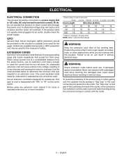
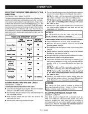
... working area. To avoid the possibility of the product plug or outlet getting wet, the operator should arrange a "drip loop" in contact with the outlet. 5 - ELECTRICAL ELECTRICAL CONNECTION This product should be connected to a power supply that it for loose or exposed wires and cut or worn insulation. **Ampere rating (on product data plate) 0-2.0 2.1-3.4 3.5-5.0 5.1-7.0 7.1-12.0 12.1-16.0 Cord Length Wire Size...
... working area. To avoid the possibility of the product plug or outlet getting wet, the operator should arrange a "drip loop" in contact with the outlet. 5 - ELECTRICAL ELECTRICAL CONNECTION This product should be connected to a power supply that it for loose or exposed wires and cut or worn insulation. **Ampere rating (on product data plate) 0-2.0 2.1-3.4 3.5-5.0 5.1-7.0 7.1-12.0 12.1-16.0 Cord Length Wire Size...
Operation Manual
Page 6
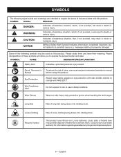
...). This product uses lithium-ion (Li-ion) batteries. Proper interpretation of risk associated with ANSI Z87.1. SYMBOL NAME DESIGNATION/EXPLANATION Safety Alert Indicates a potential personal injury hazard. Wet Conditions Alert Do not expose to a potential injury (e.g. messages relating to comply with this product. Long Hair Risk of injury, user must read and understand operator's manual before using this product. Consult...
...). This product uses lithium-ion (Li-ion) batteries. Proper interpretation of risk associated with ANSI Z87.1. SYMBOL NAME DESIGNATION/EXPLANATION Safety Alert Indicates a potential personal injury hazard. Wet Conditions Alert Do not expose to a potential injury (e.g. messages relating to comply with this product. Long Hair Risk of injury, user must read and understand operator's manual before using this product. Consult...
Operation Manual
Page 7
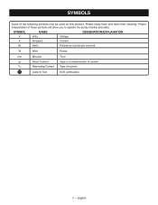
Please study them and learn their meaning. SYMBOLS Some of these symbols will allow you to operate the product better and safer. Proper interpretation of the following symbols may be used on this product. SYMBOL NAME DESIGNATION/EXPLANATION V Volts Voltage A Amperes Current Hz Hertz Frequency (cycles per second) W Watt Power min Minutes Time Direct Current Type or a characteristic of current Alternating Current Type of current Class VI Tool DOE certification 7 - English
Please study them and learn their meaning. SYMBOLS Some of these symbols will allow you to operate the product better and safer. Proper interpretation of the following symbols may be used on this product. SYMBOL NAME DESIGNATION/EXPLANATION V Volts Voltage A Amperes Current Hz Hertz Frequency (cycles per second) W Watt Power min Minutes Time Direct Current Type or a characteristic of current Alternating Current Type of current Class VI Tool DOE certification 7 - English
Operation Manual
Page 8
... charging instructions, see the operator's manuals for assistance. OPERATION WARNING: Do not allow familiarity with this manual. Remember that battery pack is sufficient to do so could cause serious personal injury. WARNING: Always remove battery pack or unplug power cord from sinks and bathtubs. Failure to inflict serious injury. APPLICATIONS You may use . INSTALLING/REMOVING BATTERY PACK See Figure 1, page 13. Lock the switch trigger by...
... charging instructions, see the operator's manuals for assistance. OPERATION WARNING: Do not allow familiarity with this manual. Remember that battery pack is sufficient to do so could cause serious personal injury. WARNING: Always remove battery pack or unplug power cord from sinks and bathtubs. Failure to inflict serious injury. APPLICATIONS You may use . INSTALLING/REMOVING BATTERY PACK See Figure 1, page 13. Lock the switch trigger by...
Operation Manual
Page 9
... stop before beginning operation. To remove the power cord, unplug the cord from the power source. Press the release button on the top of the female end of the power supply cord and remove from traffic areas to prevent a tripping hazard. Insert the female end of rotation selector is squeezed. To turn the tool ON, depress the switch trigger. NOTE: Never run unless the direction...
... stop before beginning operation. To remove the power cord, unplug the cord from the power source. Press the release button on the top of the female end of the power supply cord and remove from traffic areas to prevent a tripping hazard. Insert the female end of rotation selector is squeezed. To turn the tool ON, depress the switch trigger. NOTE: Never run unless the direction...
Operation Manual
Page 10
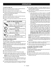
...using the switch trigger: Connect the product to an AC or DC power supply. Place the direction of rotation selector in the OFF (center lock) position . Pull the feed direction selector collar out and rotate it to the neutral (N) position. Hold the front handle with one hand...Cable N Pushed In Do Not Use ADVANCING/RETRACTING THE CABLE See Figures 4 - 6, page 14. Your drain auger is pushed in and in . English REMOVING/INSTALLING AUGER TIPS See Figure 7, page 14. OPERATION SELECTING THE RIGHT FEED AND ROTATION DIRECTION See Figures 3 and 5, pages...
...using the switch trigger: Connect the product to an AC or DC power supply. Place the direction of rotation selector in the OFF (center lock) position . Pull the feed direction selector collar out and rotate it to the neutral (N) position. Hold the front handle with one hand...Cable N Pushed In Do Not Use ADVANCING/RETRACTING THE CABLE See Figures 4 - 6, page 14. Your drain auger is pushed in and in . English REMOVING/INSTALLING AUGER TIPS See Figure 7, page 14. OPERATION SELECTING THE RIGHT FEED AND ROTATION DIRECTION See Figures 3 and 5, pages...
Operation Manual
Page 11
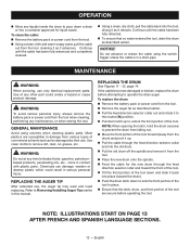
... See Figure 10, page 14. used to 2 in . wide. Hold the trigger for several seconds, allowing the obstruction to remove, change the direction of rotation selector in . NOTE: This product can be enough to 2 in the collar. To drain the drum: Remove the battery pack or power cord from the tool. Hold the tool at first. When finished, slowly...
... See Figure 10, page 14. used to 2 in . wide. Hold the trigger for several seconds, allowing the obstruction to remove, change the direction of rotation selector in . NOTE: This product can be enough to 2 in the collar. To drain the drum: Remove the battery pack or power cord from the tool. Hold the tool at first. When finished, slowly...
Operation Manual
Page 12
... old drum off the spindle and remove it from various types of commercial solvents and can damage, weaken or destroy plastic which could create a hazard or cause product damage. MAINTENANCE WARNING: When servicing, use , the auger tip may wear and need replacing. WARNING: To avoid serious personal injury, always remove the battery pack or power cord from the tool. Remove the auger tip...
... old drum off the spindle and remove it from various types of commercial solvents and can damage, weaken or destroy plastic which could create a hazard or cause product damage. MAINTENANCE WARNING: When servicing, use , the auger tip may wear and need replacing. WARNING: To avoid serious personal injury, always remove the battery pack or power cord from the tool. Remove the auger tip...
Operation Manual 1
Page 1
... to instruct others who may be used . come back on. GFCI Ground Fault Circuit Interrupter (GFCI) protection should be used , to prevent water traveling along the cord and coming in the hands of untrained users. Release button (relâchez le bouton, botón de afloje) B - Take it to an authorized serviceman when service or repair is used for the P4002. Connect...
... to instruct others who may be used . come back on. GFCI Ground Fault Circuit Interrupter (GFCI) protection should be used , to prevent water traveling along the cord and coming in the hands of untrained users. Release button (relâchez le bouton, botón de afloje) B - Take it to an authorized serviceman when service or repair is used for the P4002. Connect...
Parts Diagram
Page 1
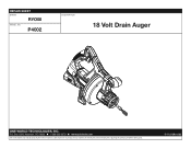
Always mention this information in all communications regarding this product and when ordering parts. 5-11-21 (Rev:02) P.O. REPAIR SHEET BRAND RYOBI MODEL NO. Box 1288, Anderson, SC 29622 1-800-525-2579 www.ryobitools.com The model number and manufacturing location will be found on a label attached to the product. P4002 DESCRIPTION 18 Volt Drain Auger ONE WORLD TECHNOLOGIES, INC.
Always mention this information in all communications regarding this product and when ordering parts. 5-11-21 (Rev:02) P.O. REPAIR SHEET BRAND RYOBI MODEL NO. Box 1288, Anderson, SC 29622 1-800-525-2579 www.ryobitools.com The model number and manufacturing location will be found on a label attached to the product. P4002 DESCRIPTION 18 Volt Drain Auger ONE WORLD TECHNOLOGIES, INC.

Parts Diagram
Page 3
... Feed Direction Selector Collar 1 1 25 720409001 Power Supply Cord 1 1 Not Shown: 1 995000294 Operator's Manual (P4002) 1 995000295 Operator's Manual (P4002PS) 1 1 1 If a key number has multiple part numbers, please order the part that corresponds with the country of origin shown on the product's data label. 3 CN = China VN = Vietnam Key No. 23) 10-CN 206700001 Motor and Gear Train Assembly 10-VN 206700010 Motor and Gear Train Assembly 11 204845001 Front Handle Assembly (Incl. PART...
... Feed Direction Selector Collar 1 1 25 720409001 Power Supply Cord 1 1 Not Shown: 1 995000294 Operator's Manual (P4002) 1 995000295 Operator's Manual (P4002PS) 1 1 1 If a key number has multiple part numbers, please order the part that corresponds with the country of origin shown on the product's data label. 3 CN = China VN = Vietnam Key No. 23) 10-CN 206700001 Motor and Gear Train Assembly 10-VN 206700010 Motor and Gear Train Assembly 11 204845001 Front Handle Assembly (Incl. PART...
Parts Diagram
Page 4
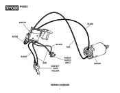
P4002 SWITCH BLACK BLACK BLACK RED POWER SUPPLY RED INPUT CONTACT PLATE HOLDER WIRING DIAGRAM 4 BLACK MOTOR
P4002 SWITCH BLACK BLACK BLACK RED POWER SUPPLY RED INPUT CONTACT PLATE HOLDER WIRING DIAGRAM 4 BLACK MOTOR
Operation Manual 2
Page 1
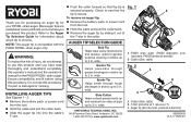
... purchased this operator's manual and the operator's manual for generic purpose cleaning in drains up to 2 in . P4002 drain auger (P4002 dégorgeoir pour tuyauterie, P4002 barrena de ...INSTALLING AUGER TIPS See Figures 1 - 2. Remove the battery pack or power cord from the tool. Hold the cable and pull the collar back. Remove the auger tip by sliding it out of pipe up to see that the tip is secure. used for the P4002 RYOBI... use this accessory. Ensure compatibility and fit before using this accessory if a part is compatible with the P4002 RYOBI...
... purchased this operator's manual and the operator's manual for generic purpose cleaning in drains up to 2 in . P4002 drain auger (P4002 dégorgeoir pour tuyauterie, P4002 barrena de ...INSTALLING AUGER TIPS See Figures 1 - 2. Remove the battery pack or power cord from the tool. Hold the cable and pull the collar back. Remove the auger tip by sliding it out of pipe up to see that the tip is secure. used for the P4002 RYOBI... use this accessory. Ensure compatibility and fit before using this accessory if a part is compatible with the P4002 RYOBI...


