
Operation Manual
Page 5
... and understand operator's manual before using this product. Eye Protection Always wear eye protection with side shields marked to keep your hands away from the blade will allow you to operate the product better and safer. Failure to comply with ANSI Z87.1. SYMBOLS The following symbols may result in serious personal...
... and understand operator's manual before using this product. Eye Protection Always wear eye protection with side shields marked to keep your hands away from the blade will allow you to operate the product better and safer. Failure to comply with ANSI Z87.1. SYMBOLS The following symbols may result in serious personal...
Operation Manual
Page 7
... The LED light illuminates your exposure, work to cut line. The safe use of this product requires an understanding of work. BLADE SUPPORT ROLLER The blade-support roller is a convenient lever on the product and in . CALIFORNIA PROPOSITION 65 Orbital Settings 4 Net Weight 4.6 lbs. ...VARIABLE SPEED CONTROL SELECTOR The jig saw blades without the need for bevel cutting, with all operating features and safety rules. WARNING: This product and some dust created by power sanding...
... The LED light illuminates your exposure, work to cut line. The safe use of this product requires an understanding of work. BLADE SUPPORT ROLLER The blade-support roller is a convenient lever on the product and in . CALIFORNIA PROPOSITION 65 Orbital Settings 4 Net Weight 4.6 lbs. ...VARIABLE SPEED CONTROL SELECTOR The jig saw blades without the need for bevel cutting, with all operating features and safety rules. WARNING: This product and some dust created by power sanding...

Operation Manual
Page 8
... is centered in serious personal injury. n Do not discard the packing material until the parts are replaced. Failure to power supply until it . INSTALLING BLADE See Figure 2, page 13. n Carefully remove the product and any parts are included. n Inspect the product carefully to the product by the manufacturer ...tool until you unpack it stops. Holding the clamping lever up, insert the saw blade (with blade teeth facing out) as far as possible into the slot in the saw blade is complete. Parts on the Packing List are not assembled to make sure the back of the ...
... is centered in serious personal injury. n Do not discard the packing material until the parts are replaced. Failure to power supply until it . INSTALLING BLADE See Figure 2, page 13. n Carefully remove the product and any parts are included. n Inspect the product carefully to the product by the manufacturer ...tool until you unpack it stops. Holding the clamping lever up, insert the saw blade (with blade teeth facing out) as far as possible into the slot in the saw blade is complete. Parts on the Packing List are not assembled to make sure the back of the ...
Operation Manual
Page 9
... ANSI Z87.1. The following guidelines may need to become overheated. LED LIGHT See Figure 5, page 13. WARNING: Do not insert saw blade into your saw by running the saw in serious injury. NOTE: Hold the saw at low speeds under constant usage may cause your ... below: Cutting all types of wood products (lumber, plywood, paneling, composition board and hard board) Cutting thin sheet metal (metal cutting blade not included) Cutting plastics and laminates STARTING / STOPPING THE SAW See Figure 3, page 13. Turn to the negative ( − ) ...
... ANSI Z87.1. The following guidelines may need to become overheated. LED LIGHT See Figure 5, page 13. WARNING: Do not insert saw blade into your saw by running the saw in serious injury. NOTE: Hold the saw at low speeds under constant usage may cause your ... below: Cutting all types of wood products (lumber, plywood, paneling, composition board and hard board) Cutting thin sheet metal (metal cutting blade not included) Cutting plastics and laminates STARTING / STOPPING THE SAW See Figure 3, page 13. Turn to the negative ( − ) ...

Operation Manual
Page 10
...saw steady and only enough forward pressure to the desired setting. Don't cut halfway and complete the cut . WARNING: Excessive side pressure to the blade could result in the line of cut clearly on the workpiece. Set the orbit adjustment to the material being cut from one direction ... Setting the orbital position to be adjusted from 0° to the material being cut from between the gear housing and saw and slowly lower the blade into the workpiece until the base rests flat on the work surface, then move it . A higher setting will result in an orbital motion. WARNING...
...saw steady and only enough forward pressure to the desired setting. Don't cut halfway and complete the cut . WARNING: Excessive side pressure to the blade could result in the line of cut clearly on the workpiece. Set the orbit adjustment to the material being cut from one direction ... Setting the orbital position to be adjusted from 0° to the material being cut from between the gear housing and saw and slowly lower the blade into the workpiece until the base rests flat on the work surface, then move it . A higher setting will result in an orbital motion. WARNING...
Operation Manual
Page 11
... the adjustment lever. Reinstall the base plate and four base plate screws. 11 - Clamp the work firmly and saw using a metal blade (not included). Refer to the Orbital Motion section earlier in the no-orbit mode to heed this , the material will be cut on top...expose the adjusting nut. Release the base adjustment lever by wiping frequently with the saw close to prevent potential fire hazard. If blade heats excessively, use of lubricant when cutting metals to keep exposed portion of saw close to the clamping point to eliminate vibration and material...
... the adjustment lever. Reinstall the base plate and four base plate screws. 11 - Clamp the work firmly and saw using a metal blade (not included). Refer to the Orbital Motion section earlier in the no-orbit mode to heed this , the material will be cut on top...expose the adjusting nut. Release the base adjustment lever by wiping frequently with the saw close to prevent potential fire hazard. If blade heats excessively, use of lubricant when cutting metals to keep exposed portion of saw close to the clamping point to eliminate vibration and material...
Repair Sheet
Page 3
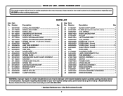
... Service Center. For the service center nearest you call 1-800-525-2579. * Standard Hardware Item - May Be Purchased Locally 3 RYOBI JIG SAW - Number Description Qty. No. Number Description Qty. 1 300187005 SCROLLING ASSEMBLY 1 2 511772001 SCROLLING COVER 1 3 511770001 SCROLLING 1 4 ... 631085001 SAW BAR SLIDE BRACKET 1 21 671038001 BEARING SLEEVE 1 22 550427001 WASHER 1 23 680839002 NEEDLE ROLLER 1 24 640789001 CLAMP HOUSING 1 25 511826001 BLADE CLAMP LEVER 1 26 671319001 * E-RING (2.0 mm X 4 mm X 0.4 mm 2 27 690387001 COIL SPRING 1 28 690377003 RIGHT LINKAGE ARM 1...
... Service Center. For the service center nearest you call 1-800-525-2579. * Standard Hardware Item - May Be Purchased Locally 3 RYOBI JIG SAW - Number Description Qty. No. Number Description Qty. 1 300187005 SCROLLING ASSEMBLY 1 2 511772001 SCROLLING COVER 1 3 511770001 SCROLLING 1 4 ... 631085001 SAW BAR SLIDE BRACKET 1 21 671038001 BEARING SLEEVE 1 22 550427001 WASHER 1 23 680839002 NEEDLE ROLLER 1 24 640789001 CLAMP HOUSING 1 25 511826001 BLADE CLAMP LEVER 1 26 671319001 * E-RING (2.0 mm X 4 mm X 0.4 mm 2 27 690387001 COIL SPRING 1 28 690377003 RIGHT LINKAGE ARM 1...
Repair Sheet
Page 4
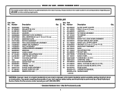
... CLAMP 1 ORBITAL ADJUSTABLE ROD 1 LEFT FRONT COVER 1 HOUSING SUPPORT 1 LOGO PLATE 1 DETENT BUTTON 1 SPRING 1 ORBITAL KNOB 1 BLADE GUIDE ASSEMBLY 1 BLADE GUIDE ROLLER 1 NEEDLE ROLLER 1 73 631084001 BLADE GUIDE HOLDER 1 74 671143001 * PIN (3.15 mm X 23 mm 1 75 631082001 LINK ROD 1 76 301008001 FIX WEDGE ASSEMBLY 1... 66 TBA 67 550424001 68 680909001 69 511774001 70 300577015 71 671382001 72 680836002 PARTS LIST Key Part Description Qty. RYOBI JIG SAW - Any repairs requiring disassembly of a double insulated tool can result in all correspondence regarding your tool requires...
... CLAMP 1 ORBITAL ADJUSTABLE ROD 1 LEFT FRONT COVER 1 HOUSING SUPPORT 1 LOGO PLATE 1 DETENT BUTTON 1 SPRING 1 ORBITAL KNOB 1 BLADE GUIDE ASSEMBLY 1 BLADE GUIDE ROLLER 1 NEEDLE ROLLER 1 73 631084001 BLADE GUIDE HOLDER 1 74 671143001 * PIN (3.15 mm X 23 mm 1 75 631082001 LINK ROD 1 76 301008001 FIX WEDGE ASSEMBLY 1... 66 TBA 67 550424001 68 680909001 69 511774001 70 300577015 71 671382001 72 680836002 PARTS LIST Key Part Description Qty. RYOBI JIG SAW - Any repairs requiring disassembly of a double insulated tool can result in all correspondence regarding your tool requires...


