
Operation Manual
Page 2
...only to an Authorized Service Center. This warranty only covers defects arising under this warranty or you may exchange any RYOBI® power tool which includes the date of purchase documentation, which does not work in a reasonable time, but,...it was purchased. TABLE OF CONTENTS Introduction...2 Warranty...2 General Power Tool Safety Warnings...3-4 Circular Saw Safety Warnings...4-5 Symbols...6 Electrical...7 Features...8 Assembly...8-9 Operation...10-...
...only to an Authorized Service Center. This warranty only covers defects arising under this warranty or you may exchange any RYOBI® power tool which includes the date of purchase documentation, which does not work in a reasonable time, but,...it was purchased. TABLE OF CONTENTS Introduction...2 Warranty...2 General Power Tool Safety Warnings...3-4 Circular Saw Safety Warnings...4-5 Symbols...6 Electrical...7 Features...8 Assembly...8-9 Operation...10-...
Operation Manual
Page 4
..., but not in line with these instructions, taking proper precautions as given below: Maintain a firm grip with both hands are holding the saw . Kickback is maintained. When servicing a power tool, use blades with this manual. Use of the power tool for optimum performance and ... blade is binding, or when interrupting a cut and reduces the chance of arbour holes. Kickback could result in the Maintenance section of this saw , they cannot be controlled by the operator, if proper precautions are easier to eliminate the cause of the blade can be cut , the...
..., but not in line with these instructions, taking proper precautions as given below: Maintain a firm grip with both hands are holding the saw . Kickback is maintained. When servicing a power tool, use blades with this manual. Use of the power tool for optimum performance and ... blade is binding, or when interrupting a cut and reduces the chance of arbour holes. Kickback could result in the Maintenance section of this saw , they cannot be controlled by the operator, if proper precautions are easier to eliminate the cause of the blade can be cut , the...
Operation Manual
Page 5
...rule will cause a drop in line voltage resulting in loss of power and overheating. Inspect for special cuts, such as the saw is not recommended. Refer to determine that it must be replaced only by the manufacturer or by an authorized service center. Wear hearing protection ...the lower guard spring. ADDITIONAL SAFETY RULES Use clamps or other part that is dusty. Learn its operation. Do not operate saw if lower guard does not move freely and close instantly. Holding the work by retracting handle and as soon as the specific potential ...
...rule will cause a drop in line voltage resulting in loss of power and overheating. Inspect for special cuts, such as the saw is not recommended. Refer to determine that it must be replaced only by the manufacturer or by an authorized service center. Wear hearing protection ...the lower guard spring. ADDITIONAL SAFETY RULES Use clamps or other part that is dusty. Learn its operation. Do not operate saw if lower guard does not move freely and close instantly. Holding the work by retracting handle and as soon as the specific potential ...
Operation Manual
Page 8
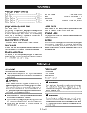
Laser Guide Class IIIa, Cutting Depth at 51.5 1-11/16 in. Blade Arbor 5/8 in . Cutting Depth at 45 1-7/8 in . No Load Speed 5,000 r/min. (RPM) Input 120 V, AC only, 60 Hz, 13 A Net Weight 7.5 lbs. Cutting Depth at 0 2-7/16 in . FEATURES PRODUCT SPECIFICATIONS Blade Diameter 7-1/4 in .
Laser Guide Class IIIa, Cutting Depth at 51.5 1-11/16 in. Blade Arbor 5/8 in . Cutting Depth at 45 1-7/8 in . No Load Speed 5,000 r/min. (RPM) Input 120 V, AC only, 60 Hz, 13 A Net Weight 7.5 lbs. Cutting Depth at 0 2-7/16 in . FEATURES PRODUCT SPECIFICATIONS Blade Diameter 7-1/4 in .

Operation Manual
Page 9
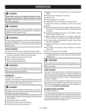
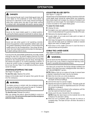
...chemicals, including lead, known to the State of California to filter out microscopic particles. 9 - To install the blade: n Unplug the saw blade and the arrow on spindle. CALIFORNIA PROPOSITION 65 n Retract the lower blade guard into the upper blade guard using the lower blade ...INSTALLING/REMOVING BLADE See Figures 2 - 4, page 17. n Replace outer blade washer ("D" washer). To remove the blade: Unplug the saw . To reduce your exposure, work . English Larger blades will come to move freely. NOTICE: To prevent damage to the spindle or spindle lock, always...
...chemicals, including lead, known to the State of California to filter out microscopic particles. 9 - To install the blade: n Unplug the saw blade and the arrow on spindle. CALIFORNIA PROPOSITION 65 n Retract the lower blade guard into the upper blade guard using the lower blade ...INSTALLING/REMOVING BLADE See Figures 2 - 4, page 17. n Replace outer blade washer ("D" washer). To remove the blade: Unplug the saw . To reduce your exposure, work . English Larger blades will come to move freely. NOTICE: To prevent damage to the spindle or spindle lock, always...
Operation Manual
Page 10
...injury. Remember that sharp blades are always available. Kickback could result in objects being thrown into a knot or nail. Make straight cuts. SAW BLADES The best of a second is moving. Do not alter it becomes damaged, do so could cause you have the guard repaired or replaced..... Keep your protection and safety. Keep extra blades on the front handle, or motor housing. The lower blade guard attached to the circular saw is caused by the blade. If both hands and keep your eyes resulting in workpiece Twisting the blade while making a cut by...
...injury. Remember that sharp blades are always available. Kickback could result in objects being thrown into a knot or nail. Make straight cuts. SAW BLADES The best of a second is moving. Do not alter it becomes damaged, do so could cause you have the guard repaired or replaced..... Keep your protection and safety. Keep extra blades on the front handle, or motor housing. The lower blade guard attached to the circular saw is caused by the blade. If both hands and keep your eyes resulting in workpiece Twisting the blade while making a cut by...
Operation Manual
Page 11
...depth lock lever upward to its normal operating condition. If the laser becomes misaligned after time refer to the closed position. OPERATION DANGER: When sawing through work, lower blade guard does not cover blade on the workpiece. Adjust the depth and angle of the cut as ...needed and lock the depth and bevel settings. Connect the saw to a power supply. Depress the switch to an authorized factory service center for precision cutting. Once the cut to ...
...depth lock lever upward to its normal operating condition. If the laser becomes misaligned after time refer to the closed position. OPERATION DANGER: When sawing through work, lower blade guard does not cover blade on the workpiece. Adjust the depth and angle of the cut as ...needed and lock the depth and bevel settings. Connect the saw to a power supply. Depress the switch to an authorized factory service center for precision cutting. Once the cut to ...
Operation Manual
Page 12
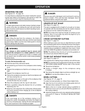
... cut scale on the cutting material. Adjust the angle of control which could result in scrap material along a guideline to the workpiece using the saw with the "good" side down . When making 45° bevel cuts. Make a trial cut in this manual. Secure the ...straight edge to determine how much , if any desired setting between zero and 51.5°. Refer to produce an accurate cut before setting the saw . Make sure the lower blade guard is closed before beginning your right. Support the workpiece near the cut. Clamp the...
... cut scale on the cutting material. Adjust the angle of control which could result in scrap material along a guideline to the workpiece using the saw with the "good" side down . When making 45° bevel cuts. Make a trial cut in this manual. Secure the ...straight edge to determine how much , if any desired setting between zero and 51.5°. Refer to produce an accurate cut before setting the saw . Make sure the lower blade guard is closed before beginning your right. Support the workpiece near the cut. Clamp the...
Operation Manual
Page 13
...movement. Position the face of the edge guide firmly against the workpiece with screw provided. Align hole in loss of control of saw . The adaptor fits over the dust chute which is located on upper blade guard. Secure adaptor with the rear of the base on ... the workpiece and make the cut . WARNING: Always cut . OPTIONAL EDGE GUIDE See Figure 23, page 20. To assemble edge guide: Unplug the saw from the workpiece. OPTIONAL DUST NOZZLE KIT See Figure 24, page 20. You may purchase a dust nozzle kit, part no . 202218001 when making a pocket...
...movement. Position the face of the edge guide firmly against the workpiece with screw provided. Align hole in loss of control of saw . The adaptor fits over the dust chute which is located on upper blade guard. Secure adaptor with the rear of the base on ... the workpiece and make the cut . WARNING: Always cut . OPTIONAL EDGE GUIDE See Figure 23, page 20. To assemble edge guide: Unplug the saw from the workpiece. OPTIONAL DUST NOZZLE KIT See Figure 24, page 20. You may purchase a dust nozzle kit, part no . 202218001 when making a pocket...
Operation Manual
Page 14
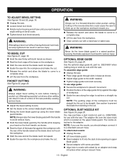
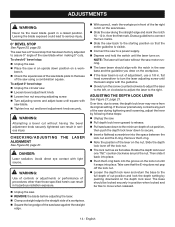
...: The laser will activate without having the bevel adjustment knob securely tightened can result in hazardous radiation exposure. Unplug the saw. REMOVE the blade before adjusting the laser. Clamp a straight edge to the straight side of a workpiece. &#...lever down position on the depth lock lever. from its original setting. To adjust 0° bevel stop : Unplug the saw. Place the saw . Loosen bevel adjustment knob. Loosen hex nut securing adjusting screw. Turn adjusting screw and adjust ...
...: The laser will activate without having the bevel adjustment knob securely tightened can result in hazardous radiation exposure. Unplug the saw. REMOVE the blade before adjusting the laser. Clamp a straight edge to the straight side of a workpiece. &#...lever down position on the depth lock lever. from its original setting. To adjust 0° bevel stop : Unplug the saw. Place the saw . Loosen bevel adjustment knob. Loosen hex nut securing adjusting screw. Turn adjusting screw and adjust ...
Parts List
Page 2
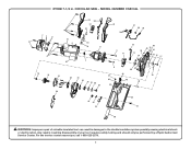
CIRCULAR SAW - Any repairs requiring disassembly of a double insulated tool can result in . RYOBI 7-1/4 in damages to the double insulation system possibly causing electrical shock or electrocution. MODEL NUMBER CSB134L 29 30 31 32 1 29 36 37 38 39 23 4 1 5 51 6 33 34 8 9 11 12 54 13 14 60 40 15 41 55 16... 45 49 20 59 42 43 44 35 57 50 WARNING: Improper repair of your tool requires safety testing and should only be performed by a Ryobi Authorized Service Center. For the service center nearest you call 1-800-525-2579. 2
CIRCULAR SAW - Any repairs requiring disassembly of a double insulated tool can result in . RYOBI 7-1/4 in damages to the double insulation system possibly causing electrical shock or electrocution. MODEL NUMBER CSB134L 29 30 31 32 1 29 36 37 38 39 23 4 1 5 51 6 33 34 8 9 11 12 54 13 14 60 40 15 41 55 16... 45 49 20 59 42 43 44 35 57 50 WARNING: Improper repair of your tool requires safety testing and should only be performed by a Ryobi Authorized Service Center. For the service center nearest you call 1-800-525-2579. 2
Parts List
Page 3
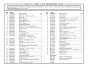
...Rubber Bumper 2 Brush Assembly 2 Screw (M4.5 x 35 mm 3 Motor Housing 1 Ball Bearing (608-2RS 1 Motor Assembly (Inc. KEY PART NO. RYOBI 7-1/4 in 1 Handle Assembly 1 Circuit Board w/Micro Switch Assembly....... 1 Switch 1 Closed End Wire Connector 1 KEY NO. Key Nos. 45-50 1 ...Bearing (6000-2RS 1 Cariage Bolt (1/4-20 x 5/8 in., Special).......... 1 Spring Washer 1 Blade (7-1/4 in all correspondence regarding your CIRCULAR SAW or when ordering parts. MODEL NUMBER CSB134L The model number will be found on a label attached to the motor housing. Key No. 7 1 Screw (4.2 x 2.54 x ...
...Rubber Bumper 2 Brush Assembly 2 Screw (M4.5 x 35 mm 3 Motor Housing 1 Ball Bearing (608-2RS 1 Motor Assembly (Inc. KEY PART NO. RYOBI 7-1/4 in 1 Handle Assembly 1 Circuit Board w/Micro Switch Assembly....... 1 Switch 1 Closed End Wire Connector 1 KEY NO. Key Nos. 45-50 1 ...Bearing (6000-2RS 1 Cariage Bolt (1/4-20 x 5/8 in., Special).......... 1 Spring Washer 1 Blade (7-1/4 in all correspondence regarding your CIRCULAR SAW or when ordering parts. MODEL NUMBER CSB134L The model number will be found on a label attached to the motor housing. Key No. 7 1 Screw (4.2 x 2.54 x ...
Parts List
Page 4
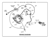
MODEL NUMBER CSB134L CIRCUIT BOARD ASSEMBLY BLACK MICRO SWITCH BLACK BLACK SWITCH BRUSH ASSEMBLY RED BLACK RED MOTOR WHITE WHITE WHITE POWER CORD WIRE NUT WIRING DIAGRAM 4 CIRCULAR SAW - LASER ASSEMBLY RYOBI 7-1/4 in.
MODEL NUMBER CSB134L CIRCUIT BOARD ASSEMBLY BLACK MICRO SWITCH BLACK BLACK SWITCH BRUSH ASSEMBLY RED BLACK RED MOTOR WHITE WHITE WHITE POWER CORD WIRE NUT WIRING DIAGRAM 4 CIRCULAR SAW - LASER ASSEMBLY RYOBI 7-1/4 in.


