Operation Manual
Page 8
... directional arrow. n Align perimeter of the arrow. INSTALLING/REPLACING SANDING BELT See Figure 5, page 15. The sanding belt must run in a hazardous condition leading to avoid personal injury. 8 - n Place the sanding belt over the drive roller and idler roller with the saw: Key No. n Remove ...the backing from carton and place on both drums. n Push the belt tension lever back into position. WARNING: If any parts are replaced....
... directional arrow. n Align perimeter of the arrow. INSTALLING/REPLACING SANDING BELT See Figure 5, page 15. The sanding belt must run in a hazardous condition leading to avoid personal injury. 8 - n Place the sanding belt over the drive roller and idler roller with the saw: Key No. n Remove ...the backing from carton and place on both drums. n Push the belt tension lever back into position. WARNING: If any parts are replaced....
Operation Manual
Page 11
...belt/disc sander. n Plug in the OFF ( O ) position. Readjust tracking knob if necessary. n Unplug the belt... sanding belt. Applying... belt to...belt tracking: n Turn the switch ON and then immediately turn . n If the sanding belt...belt while applying only enough pressure to allow the sanding belt to heed this warning could result in serious personal injury. To adjust belt tracking: n If the sanding belt...BELT TRACKING See Figure 20, page 19. n Turn the switch ON and then immediately OFF again, noting belt movement. OPERATION SURFACE SANDING ON THE SANDING BELT... the belt tends ...
...belt/disc sander. n Plug in the OFF ( O ) position. Readjust tracking knob if necessary. n Unplug the belt... sanding belt. Applying... belt to...belt tracking: n Turn the switch ON and then immediately turn . n If the sanding belt...belt while applying only enough pressure to allow the sanding belt to heed this warning could result in serious personal injury. To adjust belt tracking: n If the sanding belt...BELT TRACKING See Figure 20, page 19. n Turn the switch ON and then immediately OFF again, noting belt movement. OPERATION SURFACE SANDING ON THE SANDING BELT... the belt tends ...
Operation Manual
Page 12
... the tool is unplugged from various types of commercial solvents and may be damaged by squeezing the belt with side shields marked to loosen the belt tension. CHANGING DRIVE BELT See Figure 22, page 19. n Remove the old drive belt. MAINTENANCE WARNING: When servicing, use . n Using a phillips head screwdriver, remove the screw in contact with plastic...
... the tool is unplugged from various types of commercial solvents and may be damaged by squeezing the belt with side shields marked to loosen the belt tension. CHANGING DRIVE BELT See Figure 22, page 19. n Remove the old drive belt. MAINTENANCE WARNING: When servicing, use . n Using a phillips head screwdriver, remove the screw in contact with plastic...
Repair Sheet
Page 4
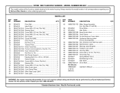
... NUMBER BD4601 The model number will be performed by a Ryobi Authorized Service Center. PARTS LIST KEY NO. 60 61 62 63 64 65 66 67 68 69 70 71 72 73 74 75 76 77 78 79 80 81 82 83 84 PART NUMBER DESCRIPTION QTY. BD46075 Drive Belt 1 ... all correspondence regarding your tool requires safety testing and should only be found on a label attached to the motor housing. Hd 1 089027001041 Belt Guard 1 089027001042 Square Nut (M8 1 BD46076 Drive Pulley 1 BD46043 Roll Pin (5 x 8 2 BD46044 Tension Plate 1 089027001701 Motor Assembly 1 089027001708 Power Cord w/Label (Inc. May Be ...
... NUMBER BD4601 The model number will be performed by a Ryobi Authorized Service Center. PARTS LIST KEY NO. 60 61 62 63 64 65 66 67 68 69 70 71 72 73 74 75 76 77 78 79 80 81 82 83 84 PART NUMBER DESCRIPTION QTY. BD46075 Drive Belt 1 ... all correspondence regarding your tool requires safety testing and should only be found on a label attached to the motor housing. Hd 1 089027001041 Belt Guard 1 089027001042 Square Nut (M8 1 BD46076 Drive Pulley 1 BD46043 Roll Pin (5 x 8 2 BD46044 Tension Plate 1 089027001701 Motor Assembly 1 089027001708 Power Cord w/Label (Inc. May Be ...


