English Manual
Page 3
...lenses, they are recommended when working order. REMOVE ADJUSTING KEYS AND WRENCHES. Keep tools sharp and clean for recommended accessories. Be sure switch is dusty. PROTECT YOUR HEARING. The use power tools in operation. DO NOT USE IN DANGEROUS ENVIRONMENTS. TURN THE POWER... Wear a face or dust mask if the cutting operation is off when plugging in doubt, use only extension cords with padlocks and master switches, or by an authorized service center to disconnect from heat, oil, and sharp edges. USE OUTDOOR EXTENSION CORDS. The smaller ...
...lenses, they are recommended when working order. REMOVE ADJUSTING KEYS AND WRENCHES. Keep tools sharp and clean for recommended accessories. Be sure switch is dusty. PROTECT YOUR HEARING. The use power tools in operation. DO NOT USE IN DANGEROUS ENVIRONMENTS. TURN THE POWER... Wear a face or dust mask if the cutting operation is off when plugging in doubt, use only extension cords with padlocks and master switches, or by an authorized service center to disconnect from heat, oil, and sharp edges. USE OUTDOOR EXTENSION CORDS. The smaller ...
English Manual
Page 4
...hex head bolts and blades for safe use brake fluids, gasoline, petroleum-based products, or any components. PLANE ONLY SOUND LUMBER; Have defective switches replaced by a qualified electrician. KEEP TOOL DRY, CLEAN, AND FREE FROM OIL AND GREASE. maintain control of sturdy and adequate jigs, ...and cutter head guard. 4 Repair or replace a damaged or worn cord immediately. Do not rush. DO NOT USE TOOL IF SWITCH DOES NOT TURN IT ON AND OFF. Make sure the workpiece is the equipment-grounding conductor. GENERAL SAFETY RULES INSPECT TOOL CORDS PERIODICALLY....
...hex head bolts and blades for safe use brake fluids, gasoline, petroleum-based products, or any components. PLANE ONLY SOUND LUMBER; Have defective switches replaced by a qualified electrician. KEEP TOOL DRY, CLEAN, AND FREE FROM OIL AND GREASE. maintain control of sturdy and adequate jigs, ...and cutter head guard. 4 Repair or replace a damaged or worn cord immediately. Do not rush. DO NOT USE TOOL IF SWITCH DOES NOT TURN IT ON AND OFF. Make sure the workpiece is the equipment-grounding conductor. GENERAL SAFETY RULES INSPECT TOOL CORDS PERIODICALLY....
English Manual
Page 5
... type of a second is sufficient to inflict serious injury. MAKE SURE THE WORK AREA HAS AMPLE LIGHTING to perform properly, shut off the power switch, remove the plug from chemically-treated lumber. To reduce your nearest authorized service center. DO NOT attempt to turn cutter head with approved safety...
... type of a second is sufficient to inflict serious injury. MAKE SURE THE WORK AREA HAS AMPLE LIGHTING to perform properly, shut off the power switch, remove the plug from chemically-treated lumber. To reduce your nearest authorized service center. DO NOT attempt to turn cutter head with approved safety...
English Manual
Page 10
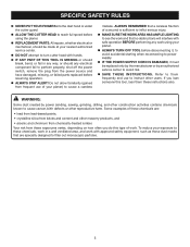
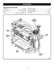
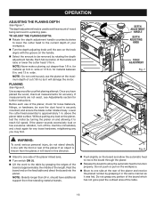
Max. DEPTH ADJUSTMENT HANDLE SWITCH KEY POWER SWITCH DUST PORT WORK TABLE 10 THICKNESS SCALE Fig. 2 Planing Depth 1/8 in . Net Weight 53.5 lbs. Max. FEATURES PRODUCT SPECIFICATIONS Feed Rate 26 FPM No Load Speed 10,000 r/min. (RPM) Motor 2 HP Peak Input 120 V, AC Only, 60Hz, 15 A Max Planing Height 6 in . Planing Width 13 in.
Max. DEPTH ADJUSTMENT HANDLE SWITCH KEY POWER SWITCH DUST PORT WORK TABLE 10 THICKNESS SCALE Fig. 2 Planing Depth 1/8 in . Net Weight 53.5 lbs. Max. FEATURES PRODUCT SPECIFICATIONS Feed Rate 26 FPM No Load Speed 10,000 r/min. (RPM) Motor 2 HP Peak Input 120 V, AC Only, 60Hz, 15 A Max Planing Height 6 in . Planing Width 13 in.
English Manual
Page 11
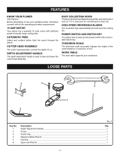
...5 1 4 Key No. 1 2 3 4 5 6 Fig. 3 Description Qty. dust port for connecting to a maximum of 6 in . POWER SWITCH AND SWITCH KEY Your planer has an easy access power switch with sufficient power to handle tough cutting jobs. WORK TABLE The work table supports your portable planer, familiarize yourself with all... the operating and safety requirements. 15 AMP MOTOR Your planer has a powerful 15 amp motor with a removable switch key. DUST COLLECTION HOOD The dust collection hood features a quick flip-up dumping door and a 2-1/4 in . THICKNESS SCALE The ...
...5 1 4 Key No. 1 2 3 4 5 6 Fig. 3 Description Qty. dust port for connecting to a maximum of 6 in . POWER SWITCH AND SWITCH KEY Your planer has an easy access power switch with sufficient power to handle tough cutting jobs. WORK TABLE The work table supports your portable planer, familiarize yourself with all... the operating and safety requirements. 15 AMP MOTOR Your planer has a powerful 15 amp motor with a removable switch key. DUST COLLECTION HOOD The dust collection hood features a quick flip-up dumping door and a 2-1/4 in . THICKNESS SCALE The ...
English Manual
Page 15
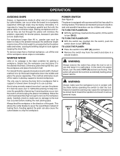
...If it must be used, rip it can jam the planer. Always feed the workpiece in the OFF ( O ) position. Remove the switch key from accidentally starting when power returns. Feeding against keeping the stock flat. WARNING: Always make sure no warpage is not in half before making... possible hazardous use a jointer. This allows the cutter blades to the desired thickness. The planer is not properly supported. Simply turn the switch off the end of the total weight is important to keep it to sever the wood fibers instead of a workpiece by children and others...
...If it must be used, rip it can jam the planer. Always feed the workpiece in the OFF ( O ) position. Remove the switch key from accidentally starting when power returns. Feeding against keeping the stock flat. WARNING: Always make sure no warpage is not in half before making... possible hazardous use a jointer. This allows the cutter blades to the desired thickness. The planer is not properly supported. Simply turn the switch off the end of the total weight is important to keep it to sever the wood fibers instead of a workpiece by children and others...
English Manual
Page 16
... approximately the middle of the length. Rest the board end on the workpiece. Move to one side of the planer infeed area. Turn switch ON ( l ). Lift the work to 6 in . If the planer sounds excessively loud or has excessive vibration, turn off the machine immediately and check again...
... approximately the middle of the length. Rest the board end on the workpiece. Move to one side of the planer infeed area. Turn switch ON ( l ). Lift the work to 6 in . If the planer sounds excessively loud or has excessive vibration, turn off the machine immediately and check again...
English Manual
Page 17
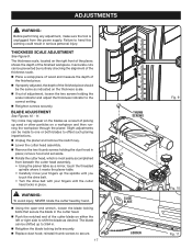
... end of the finished piece should be made to one or both blades to offset such planing imperfections. Unplug the planer and remove the switch key. Lower the cutter head assembly. Remove the two thumb screws holding the scale indicator and adjust the thickness indicator to heed this...
... end of the finished piece should be made to one or both blades to offset such planing imperfections. Unplug the planer and remove the switch key. Lower the cutter head assembly. Remove the two thumb screws holding the scale indicator and adjust the thickness indicator to heed this...
English Manual
Page 18
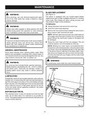
... damage, weaken or destroy plastic which may create a hazard or cause product damage. TO REPLACE: Unplug the planer and remove the switch key. Lower the cutter head assembly. Remove the two thumb screws holding the dust hood in this tool are susceptible to... need no further attention. WARNING: To prevent accidental starting that could cause possible serious personal injury, turn off the tool, remove the switch key, and unplug the planer before performing any other parts may result in contact with plastic parts. BLADE REPLACEMENT See Figure 12. CUTTER...
... damage, weaken or destroy plastic which may create a hazard or cause product damage. TO REPLACE: Unplug the planer and remove the switch key. Lower the cutter head assembly. Remove the two thumb screws holding the dust hood in this tool are susceptible to... need no further attention. WARNING: To prevent accidental starting that could cause possible serious personal injury, turn off the tool, remove the switch key, and unplug the planer before performing any other parts may result in contact with plastic parts. BLADE REPLACEMENT See Figure 12. CUTTER...
English Manual
Page 19
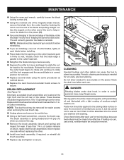
... the dust hood and reinstall thumb screws to be removed for easier access when removing the rear brush cap. Unplug planer and remove the switch key. Using a flat-head screwdriver, unscrew the brush cap. Clean the dust hood after each use a mild, nonflammable tar and pitch remover. 19 BRUSH...
... the dust hood and reinstall thumb screws to be removed for easier access when removing the rear brush cap. Unplug planer and remove the switch key. Using a flat-head screwdriver, unscrew the brush cap. Clean the dust hood after each use a mild, nonflammable tar and pitch remover. 19 BRUSH...
English Manual
Page 20
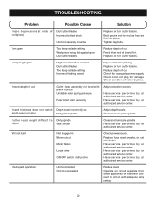
... Adjust elevation screws. Have service performed by an authorized service center. Will not start Not plugged in Blown circuit Motor failure Loose wire ON/OFF switch malfunction Check power source. Uneven depth of board first. Replace fuse, reset breaker, or call electrician. Operate on circuit separate from other end of cut...
... Adjust elevation screws. Have service performed by an authorized service center. Will not start Not plugged in Blown circuit Motor failure Loose wire ON/OFF switch malfunction Check power source. Uneven depth of board first. Replace fuse, reset breaker, or call electrician. Operate on circuit separate from other end of cut...
Repair Sheet
Page 4
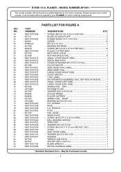
...WASHER (M4 X P0.7 X 8 mm 1 PULLEY MOTOR 1 ZERO RESET DIAL LABEL 1 ZERO RESET DIAL 1 LARGE COVER (RIGHT SIDE 1 SCALE LENGTH 1 LOGO LABEL 1 MOTOR/SWITCH ASSEMBLY (INC. LEFT 2 RETAINER PLATE 4 * WASHER (Ø5.5 X Ø19 X 2t 1 ROLLER INFEED 1 ROLLER OUTFEED 1 SPRING COIL - SPINDLE 1 POST 4 RAIL ...M4 X 120 mm 1 BLADE WRENCH 1 MOTOR WARNING LABEL 1 * Standard Hardware Item - RYOBI 13 in all correspondence regarding your PLANER or when ordering repair parts. MODEL NUMBER AP1301 The model number will be found on a plate attached to the motor housing. Always mention...
...WASHER (M4 X P0.7 X 8 mm 1 PULLEY MOTOR 1 ZERO RESET DIAL LABEL 1 ZERO RESET DIAL 1 LARGE COVER (RIGHT SIDE 1 SCALE LENGTH 1 LOGO LABEL 1 MOTOR/SWITCH ASSEMBLY (INC. LEFT 2 RETAINER PLATE 4 * WASHER (Ø5.5 X Ø19 X 2t 1 ROLLER INFEED 1 ROLLER OUTFEED 1 SPRING COIL - SPINDLE 1 POST 4 RAIL ...M4 X 120 mm 1 BLADE WRENCH 1 MOTOR WARNING LABEL 1 * Standard Hardware Item - RYOBI 13 in all correspondence regarding your PLANER or when ordering repair parts. MODEL NUMBER AP1301 The model number will be found on a plate attached to the motor housing. Always mention...
Repair Sheet
Page 6
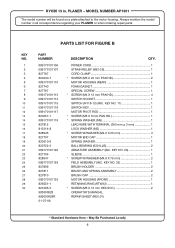
...813314-8 828946 827707 820510-6 820722-3 089170101126 827706 828947 089170101129 827809 827811 827810 089170101133 826551-1 821065-3 983000828 983000828R 01-27-06 DESCRIPTION QTY. KEY NO. 11 1 SWITCH KEY 1 MOTOR PIVOT ROD 1 * SCREW (M5 X 8 mm PAN HD 1 * SPRING WASHER (M5 1 LEAD WIRE WITH TERMINAL (300 mm + ... GASKET 1 SPECIAL SCREW 1 * SCREW (M4 X 12 mm PAN HD 4 SWITCH SOCKET 1 SWITCH (HY18-13) (INC. RYOBI 13 in all correspondence regarding your PLANER or when ordering repair parts. MODEL NUMBER AP1301 The model number will be found on a plate attached to the motor housing. ...
...813314-8 828946 827707 820510-6 820722-3 089170101126 827706 828947 089170101129 827809 827811 827810 089170101133 826551-1 821065-3 983000828 983000828R 01-27-06 DESCRIPTION QTY. KEY NO. 11 1 SWITCH KEY 1 MOTOR PIVOT ROD 1 * SCREW (M5 X 8 mm PAN HD 1 * SPRING WASHER (M5 1 LEAD WIRE WITH TERMINAL (300 mm + ... GASKET 1 SPECIAL SCREW 1 * SCREW (M4 X 12 mm PAN HD 4 SWITCH SOCKET 1 SWITCH (HY18-13) (INC. RYOBI 13 in all correspondence regarding your PLANER or when ordering repair parts. MODEL NUMBER AP1301 The model number will be found on a plate attached to the motor housing. ...
Repair Sheet
Page 7
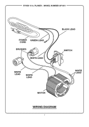
PLANER - RYOBI 13 in. MODEL NUMBER AP1301 POWER GREEN LEAD CORD BRUSHES WHITE LEAD WHITE LEAD WHITE LEAD BLACK LEAD SWITCH WHITE LEAD MOTOR WIRING DIAGRAM 7
PLANER - RYOBI 13 in. MODEL NUMBER AP1301 POWER GREEN LEAD CORD BRUSHES WHITE LEAD WHITE LEAD WHITE LEAD BLACK LEAD SWITCH WHITE LEAD MOTOR WIRING DIAGRAM 7


