Ryobi AP1301 Support Question
Ryobi AP1301 Support Question
Find answers below for this question about Ryobi AP1301.Need a Ryobi AP1301 manual? We have 4 online manuals for this item!
Question posted by adriaanbwr on April 3rd, 2022
I Need Wiring Diagram For Switch With Reset Button. While Replacing The Amature
The wires came loose while replacing the amature
Current Answers
Answer #1: Posted by akanetuk1 on April 3rd, 2022 7:07 AM
akanetuk1

Member since:
February 6th, 2022 Points: 176,800

Member since:
February 6th, 2022 Points: 176,800
Check out the wiring diagram here: https://www.manualslib.com/manual/376478/Ryobi-Ap1301.html?page=7
Answer #2: Posted by SonuKumar on April 3rd, 2022 7:28 AM
SonuKumar

Member since:
May 9th, 2021 Points: 16,604,800
Member since:
May 9th, 2021 Points: 16,604,800
Please respond to my effort to provide you with the best possible solution by using the "Acceptable Solution" and/or the "Helpful" buttons when the answer has proven to be helpful.
Regards,
Sonu
Your search handyman for all e-support needs!!
Related Ryobi AP1301 Manual Pages
English Manual - Page 2
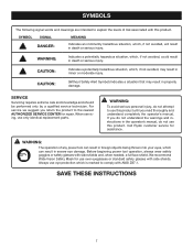
... Authorized Service Centers.
One World Technologies, Inc. To receive a replacement power tool or requested warranty service, you must present proof of purchase and return ...61550; Electrical ...8 � Glossary of Terms...9 � Features...10-11 Loose Parts ...11 � Assembly ...12-13 � Operation...14-16 Adjustments...
English Manual - Page 3
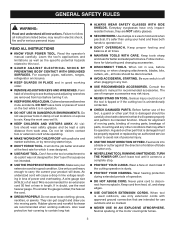
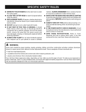
...TOOLS. Don't force the tool or attachment to operate tool.
DON'T OVERREACH. Be sure switch...tools should be properly repaired or replaced by removing starter keys.
DON'T FORCE TOOL. Serious injury could ignite fumes.
3 Feed work area. Don't leave tool until it was designed.
USE RIGHT TOOL....
MAINTAIN TOOLS WITH CARE. A wire gauge size (A.W.G.) of...
English Manual - Page 4
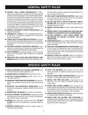
...61550; USE ONLY CORRECT ELECTRICAL DEVICES: 3-wire extension cords that have repaired by a ...section. Have defective switches replaced by a qualified electrician.
KEEP TOOL DRY, CLEAN,...replace a damaged or worn cord immediately.
If tool is equipped with threeprong plug, it well away from nails, screws, stones, or other parts may cause the risk of accessories are no loose...
English Manual - Page 5
...any work . ALWAYS REMEMBER that a careless fraction of your planer.
ALWAYS TURN OFF TOOL before disconnecting it, to avoid accidental starting when reconnecting to power supply.
IF THE... to perform properly, shut off the power switch, remove the plug from the power source and have damaged, missing, or failed parts replaced before resuming operation.
ALWAYS STAY ALERT...
English Manual - Page 7
...signal words and meanings are intended to explain the levels of any power tool can result in foreign objects being thrown into your eyes, which can ...tool operation, always wear safety goggles or safety glasses with this product. WARNING:
The operation of risk associated with side shields and, when needed, a full face shield.
Call Ryobi customer service for use only identical replacement...
English Manual - Page 8
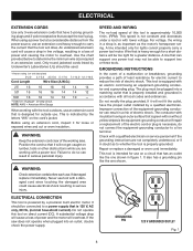
... motor will be plugged into an outlet, double check the power supply.
If damaged replace immediately. When using an extension cord, inspect it for electric current to carry the ... lumber, tools or other obstructions while you are not completely understood, or if in a loss of least resistance for loose or exposed wires and cut or worn insulation.
Before using a power tool at a...
English Manual - Page 10
FEATURES
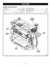
PRODUCT SPECIFICATIONS
Feed Rate 26 FPM No Load Speed 10,000 r/min. (RPM) Motor 2 HP Peak Input 120 V, AC Only, 60Hz, 15 A
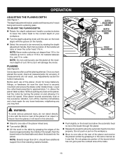
Max Planing Height 6 in . Max. Net Weight 53.5 lbs. Planing Depth 1/8 in . DEPTH ADJUSTMENT
HANDLE
SWITCH KEY
POWER SWITCH
DUST PORT
WORK TABLE
10
THICKNESS SCALE
Fig. 2 Max. Planing Width 13 in.
English Manual - Page 11
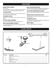
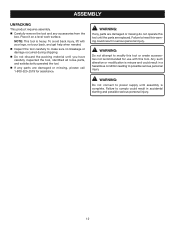
...a quick flip-up dumping door and a 2-1/4 in .
Depth Adjustment Handle ...1
Screw ...1
Switch Key...1
Magnetic Blade Wrench ...1
Hex Key ...1
Open-end Wrench ...1
11
WORK TABLE
The ...all the operating and safety requirements.
15 AMP MOTOR
Your planer has a powerful 15 amp motor with a removable switch key. LOOSE PARTS
3
2
6
5 1
4
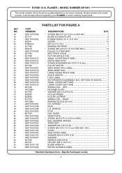
Key No. 1 2 3 4 5 6
Fig. 3
Description
Qty....
English Manual - Page 12
... carefully inspected the tool, identified all loose parts, and satisfactorily operated the tool.
If any accessories from the box. NOTE: This tool is complete.
Failure...needed.
Inspect the tool carefully to heed this tool until the parts are replaced. Place it on a level work surface. To avoid back injury, lift with this tool.
WARNING:
Do not attempt to modify this tool...
English Manual - Page 14
...their wear.
Refer to the Maintenance section of this tool for instructions on how to remove and replace or turn the cutter blades. WARNING:
Do not use any ...the planer starting with light planing cuts first.
WARNING:
Always wear safety goggles or safety glasses with loose knots or foreign objects. WARNING:
The use this operator's manual for the purpose listed below: ...
English Manual - Page 15
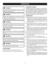
... the desired thickness. OPERATION
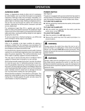
AVOIDING SNIPE
Snipes, or depressions made at either end of jamming. Although snipe may cause the workpiece to the tool has occurred before operating the switch to remove the workpiece easily.
WARPED WOOD
Little or no damage to be barely noticeable, it provides a more of the workpiece where...
English Manual - Page 16
... stands.
Push slightly on the feed table and direct the board into the planer. for loose fasteners, fittings, or hardware; Do not push or pull on the knob aligns with the front or...of the length. If an object is used to one side of the planer infeed area.
Turn switch ON ( l ).
Lift the work to the table by rotating the depth adjustment handle. should have...
English Manual - Page 17
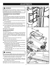
... to offset such planing imperfections. Unplug the planer and remove the switch key. Lower the cutter head assembly. Remove the two... screws to 3/64 in.
Retighten the blade locking bolts securely. Replace dust hood; BLADE ADJUSTMENT
See Figures 10 - 11.
remove hood and set aside.... tool is most easily accomplished
from the power supply.
English Manual - Page 18
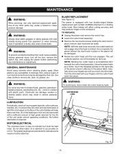
...need no further attention.
A
light film of commercial solvents and may create a hazard or cause product damage.
GENERAL MAINTENANCE
Avoid using solvents when cleaning plastic parts. TO REPLACE: Unplug the planer and remove the switch..., gasoline, petroleumbased products, penetrating oils, etc., come in this tool are susceptible to the planer table.
All of the unit under ...
English Manual - Page 19
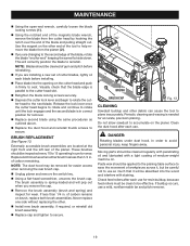
...lock engages and the second blade is needed for removal.
Replace second blade using the same procedures as outlined above.
Replace the dust hood and reinstall thumb ...planer and remove the switch key.
Using a flat-head screwdriver, unscrew the brush cap. Never replace one side without replacing the other debris can cause the tool to plane inaccurately.
MAINTENANCE...
English Manual - Page 20
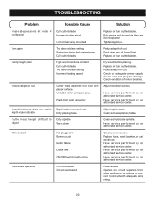
...not start
Not plugged in Blown circuit Motor failure Loose wire ON/OFF switch malfunction
Check power source. Have service performed by...adequate amp rating.
20 Uneven depth of cut . Replace or turn cutter blades.
Butt pieces end-to Dirty ...)
Incorrect butted stock
Unit not securely mounted
Replace or turn cutter blades. Replace or turn cutter blades. TROUBLESHOOTING
Problem
Possible ...
English Manual - Page 22
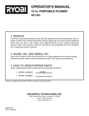
... be found on a plate attached to provide all pertinent facts when you have purchased your tool, should a need ever exist for your nearest Authorized Service Center. The model number of Authorized Service Centers.
• MODEL NO. PORTABLE PLANER
AP1301
• SERVICE
Now that you call 1-800-525-2579 for repair parts or service...
Repair Sheet - Page 4
... LABEL 1
ZERO RESET DIAL 1 LARGE COVER (RIGHT SIDE 1 SCALE LENGTH 1
LOGO LABEL 1 MOTOR/SWITCH ASSEMBLY (INC. SPINDLE 1
BASE 1 L.H.
HD 2
CHAIN 1 SIDE COVER LABEL 2 * WASHER (Ø10.5 X Ø21 X 2t 4
WASHER 1 WRENCH (M8 X M10 1
HEX KEY (M4 X 120 mm 1 BLADE WRENCH 1 MOTOR WARNING LABEL 1
* Standard Hardware Item - MODEL NUMBER AP1301
The model number will...
Repair Sheet - Page 6
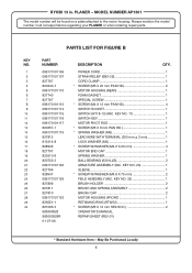
...1 * SCREW W/WASHER (M4.8 X 75 mm 2 FIELD ASSEMBLY (INC. May Be Purchased Locally 6 MODEL NUMBER AP1301
The model number will be found on a plate attached to the motor housing. KEY NO.
1 2 3 4 5... 983000828R 01-27-06
DESCRIPTION
QTY.
KEY NO. 11 1 SWITCH KEY 1 MOTOR PIVOT ROD 1 * SCREW (M5 X 8 mm PAN HD 1 * SPRING WASHER (M5 1 LEAD WIRE WITH TERMINAL (300 mm + 3 mm 1 LOCK WASHER (M5...
Repair Sheet - Page 7
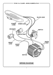
PLANER - MODEL NUMBER AP1301
POWER GREEN LEAD CORD BRUSHES
WHITE LEAD
WHITE LEAD
WHITE LEAD
BLACK LEAD
SWITCH
WHITE LEAD
MOTOR
WIRING DIAGRAM
7 RYOBI 13 in.
Similar Questions

Does Anyone Know Where To Buy A Replacement Crank Handle? Everything I Find Says
(Posted by ldwoolley 1 year ago)


I Need A Rotor For The Motor
a part of my motor portable planer
a part of my motor portable planer
(Posted by Jbgelectronica 7 years ago)

Wiring Diagram For Ryobi Rts21 Table Saw Switch
I need to view the wiring diagram for the switch on the Ryobi RTS21 table saw. I had to disconnect t...
I need to view the wiring diagram for the switch on the Ryobi RTS21 table saw. I had to disconnect t...
(Posted by wolfsonjames 9 years ago)

Overload Reset Button?
Is there an overload switch or fuse if the saw quits?
Is there an overload switch or fuse if the saw quits?
(Posted by conifir321 11 years ago)