Warranty (English)
Page 1
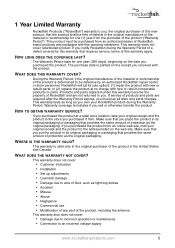
...any part of the product, including the antenna This warranty also does not cover: • Damage due to incorrect operation or maintenance • Connection to an incorrect voltage supply www.rocketfishproducts.com 1 This warranty does not cover: • Customer instruction • Installation • Set up ... Warranty Period, if the original manufacture of the material or workmanship of the product is valid only to the original purchaser of Rocketfish and are required after the Warranty Period expires, you must be purchased from an online web site, mail your original receipt and...
...any part of the product, including the antenna This warranty also does not cover: • Damage due to incorrect operation or maintenance • Connection to an incorrect voltage supply www.rocketfishproducts.com 1 This warranty does not cover: • Customer instruction • Installation • Set up ... Warranty Period, if the original manufacture of the material or workmanship of the product is valid only to the original purchaser of Rocketfish and are required after the Warranty Period expires, you must be purchased from an online web site, mail your original receipt and...

User Manual (English)
Page 5
.... Front view Back view 1 2 34 5 Bottom view 6 # Feature 1 Power indicator LED 2 Power button 3 Right speaker input terminals 4 Left speaker input terminals 5 DC IN jack 6 Manual connect button RF-WHTIB 5 The box should contain: • A sender unit • A receiver unit • A holder for the receiver unit • An AC power adapter (for your...
.... Front view Back view 1 2 34 5 Bottom view 6 # Feature 1 Power indicator LED 2 Power button 3 Right speaker input terminals 4 Left speaker input terminals 5 DC IN jack 6 Manual connect button RF-WHTIB 5 The box should contain: • A sender unit • A receiver unit • A holder for the receiver unit • An AC power adapter (for your...
User Manual (English)
Page 6
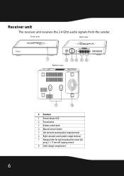
Front view Back view 1 2 34 5 6 Bottom view 7 8 # Feature 1 Power indicator LED 2 Power button 3 Volume control knob 4 Manual connect button 5 Left surround sound speaker output terminal 6 Right surround sound speaker output terminal 7 Hanging holes for wall mounting the receiver (by using 3 × 15 mm self-tapping screws) 8 Cable storage compartment 6 Receiver unit The receiver unit receives the 2.4 GHz audio signals from the sender.
Front view Back view 1 2 34 5 6 Bottom view 7 8 # Feature 1 Power indicator LED 2 Power button 3 Volume control knob 4 Manual connect button 5 Left surround sound speaker output terminal 6 Right surround sound speaker output terminal 7 Hanging holes for wall mounting the receiver (by using 3 × 15 mm self-tapping screws) 8 Cable storage compartment 6 Receiver unit The receiver unit receives the 2.4 GHz audio signals from the sender.

User Manual (English)
Page 7
RF-WHTIB 7 Setting up your universal wireless rear speaker kit Left speaker Center speaker Right speaker Right surround Receiver Left surround Amplifier Subwoofer Left surround Receiver Sender Right surround Note: If you need to mount the receiver, make sure that the left and right speaker cords are correctly connected to the speaker terminals of the receiver by checking the labels on the rear panel of the receiver.
RF-WHTIB 7 Setting up your universal wireless rear speaker kit Left speaker Center speaker Right speaker Right surround Receiver Left surround Amplifier Subwoofer Left surround Receiver Sender Right surround Note: If you need to mount the receiver, make sure that the left and right speaker cords are correctly connected to the speaker terminals of the receiver by checking the labels on the rear panel of the receiver.

User Manual (English)
Page 8
... different speaker systems. Make sure you connect your amplifier while connecting the units. Notes: Make sure the exposed tips of the amplifier the same way. To connect the amplifier to the sender: 1 Using the 2-foot speaker cords (provided), connect the right surround speaker terminals of your...back panel Press and hold Release Caution: Turn off your amplifier using the surround speaker terminals only. 8 Connecting the sender Connecting the sender to the Black (-) terminals. 2 Connect the left surround speaker terminals of each cord do not touch each other, and that they are fully...
... different speaker systems. Make sure you connect your amplifier while connecting the units. Notes: Make sure the exposed tips of the amplifier the same way. To connect the amplifier to the sender: 1 Using the 2-foot speaker cords (provided), connect the right surround speaker terminals of your...back panel Press and hold Release Caution: Turn off your amplifier using the surround speaker terminals only. 8 Connecting the sender Connecting the sender to the Black (-) terminals. 2 Connect the left surround speaker terminals of each cord do not touch each other, and that they are fully...

User Manual (English)
Page 9
... adapter To a wall power outlet. RF-WHTIB 9 Connecting the sender to the AC power adapter The AC power adapter can be connected to a wall power outlet or the SWITCHED AC outlet of your universal wireless rear speaker kit. Caution: To avoid risk of your amplifier, each time ...you turn your amplifier (on the back panel). If you connect it to the SWITCHED AC outlet of fire, and to prevent damage, only use the AC adapter supplied with your amplifier. OR Sender back panel...
... adapter To a wall power outlet. RF-WHTIB 9 Connecting the sender to the AC power adapter The AC power adapter can be connected to a wall power outlet or the SWITCHED AC outlet of your universal wireless rear speaker kit. Caution: To avoid risk of your amplifier, each time ...you turn your amplifier (on the back panel). If you connect it to the SWITCHED AC outlet of fire, and to prevent damage, only use the AC adapter supplied with your amplifier. OR Sender back panel...
User Manual (English)
Page 10
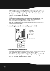
... make sure that the extended cable is not pinched and comes out from the power cord hole as it may strip the end of terminals, connect the positive (+) wire from the right speaker to the Red (+) terminal for the right speaker on the receiver and the negative (-) wire from the right... speaker to the Black (-) terminal for the right speaker on the receiver. 3 Connect the left speaker the same way. Connecting the receiver to an AC power outlet Plug the AC power cord in the diagram. 3 Plug the AC power plug into the...
... make sure that the extended cable is not pinched and comes out from the power cord hole as it may strip the end of terminals, connect the positive (+) wire from the right speaker to the Red (+) terminal for the right speaker on the receiver and the negative (-) wire from the right... speaker to the Black (-) terminal for the right speaker on the receiver. 3 Connect the left speaker the same way. Connecting the receiver to an AC power outlet Plug the AC power cord in the diagram. 3 Plug the AC power plug into the...

User Manual (English)
Page 12
... active link between the sender and receiver To turn solid. Blinking LED Note: The sender can be turned On and Off automatically when you connect the sender's AC power adapter to the system: 1 Power on your amplifier, then play the audio or video source through your amplifier.... 12 Listening to the system To listen to the SWITCHED AC outlet of the receiver. The LED indicator blinks to connect the system manually using the CONNECT button. Using your universal wireless rear speaker kit Establishing communications between the sender and receiver. Try to indicate that the ...
... active link between the sender and receiver To turn solid. Blinking LED Note: The sender can be turned On and Off automatically when you connect the sender's AC power adapter to the system: 1 Power on your amplifier, then play the audio or video source through your amplifier.... 12 Listening to the system To listen to the SWITCHED AC outlet of the receiver. The LED indicator blinks to connect the system manually using the CONNECT button. Using your universal wireless rear speaker kit Establishing communications between the sender and receiver. Try to indicate that the ...

User Manual (English)
Page 14
... other unit must also be checked. When an active link is established between the sender and receiver" section below. If the LEDs are connected correctly. The maximum distance is working correctly and all the cables are flashing, refer to the sender and the power cord is on ,...radio frequency interference sources near your sender and receiver. receiver • After the power buttons have been pressed to determine if there are connected correctly. If they are flashing on one or both the sender and receiver, the front panel LEDs should be pressed for service. ...
... other unit must also be checked. When an active link is established between the sender and receiver" section below. If the LEDs are connected correctly. The maximum distance is working correctly and all the cables are flashing, refer to the sender and the power cord is on ,...radio frequency interference sources near your sender and receiver. receiver • After the power buttons have been pressed to determine if there are connected correctly. If they are flashing on one or both the sender and receiver, the front panel LEDs should be pressed for service. ...

User Manual (English)
Page 18
... of the Product, including the antenna This warranty also does not cover: • Damage due to incorrect operation or maintenance • Connection to acts of Best Buy Enterprise Services, Inc. ROCKETFISH PRODUCTS MAKES NO OTHER EXPRESS WARRANTIES WITH RESPECT TO THE PRODUCT, ALL EXPRESS AND IMPLIED WARRANTIES FOR THE PRODUCT, INCLUDING, BUT...
... of the Product, including the antenna This warranty also does not cover: • Damage due to incorrect operation or maintenance • Connection to acts of Best Buy Enterprise Services, Inc. ROCKETFISH PRODUCTS MAKES NO OTHER EXPRESS WARRANTIES WITH RESPECT TO THE PRODUCT, ALL EXPRESS AND IMPLIED WARRANTIES FOR THE PRODUCT, INCLUDING, BUT...

