Owners Manual
Page 1
WARNING: To reduce the risk of operation, and operator safety. OPERATOR'S MANUAL 10 in. When properly cared for buying a RIDGID® product. SAVE THIS MANUAL FOR FUTURE REFERENCE Thank you for , it will give you years of rugged, trouble-free performance. TABLE SAW R4512 45 Your table saw has been engineered and manufactured to our high standards for dependability, ease of injury, the user must read and understand the operator's manual before using this product.
WARNING: To reduce the risk of operation, and operator safety. OPERATOR'S MANUAL 10 in. When properly cared for buying a RIDGID® product. SAVE THIS MANUAL FOR FUTURE REFERENCE Thank you for , it will give you years of rugged, trouble-free performance. TABLE SAW R4512 45 Your table saw has been engineered and manufactured to our high standards for dependability, ease of injury, the user must read and understand the operator's manual before using this product.
Owners Manual
Page 4
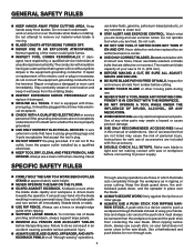
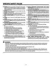
...FREE OF NAILS. Instructions for safe use of cord location and keep it should be sure all nails from contacting the saw . Through-sawing operations are tired. Stay constantly aware of accessories are not completely understood or if in doubt as in an accident ...causing possible serious personal injury. ALWAYS USE BLADE GUARD, Spreader, AND ANTIKICKBACK PAWLS on all fences and auxiliary tables before cutting. ...
...FREE OF NAILS. Instructions for safe use of cord location and keep it should be sure all nails from contacting the saw . Through-sawing operations are tired. Stay constantly aware of accessories are not completely understood or if in doubt as in an accident ...causing possible serious personal injury. ALWAYS USE BLADE GUARD, Spreader, AND ANTIKICKBACK PAWLS on all fences and auxiliary tables before cutting. ...
Owners Manual
Page 5
.... make sure the work area has ample lighting to see the work using the table saw. ALWAYS TURN OFF SAW before it must be used, including all the way past the saw blade guard and spreader/riving knife for every operation for any work and that are not listed... may cause the risk of the saw blade. NEVER reach behind, over the saw table for wide or long work pieces. AVOID KICKBACKS (work . e) Pay particular attention to instructions on the spreader/...
.... make sure the work area has ample lighting to see the work using the table saw. ALWAYS TURN OFF SAW before it must be used, including all the way past the saw blade guard and spreader/riving knife for every operation for any work and that are not listed... may cause the risk of the saw blade. NEVER reach behind, over the saw table for wide or long work pieces. AVOID KICKBACKS (work . e) Pay particular attention to instructions on the spreader/...
Owners Manual
Page 9
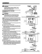
...is an optional procedure to power source until all assembly steps are not certain that secure the rear panel of the saw. Remove the panel. Lower the motor to its lowest point. Located on the top of... motor voltage from the wire connectors. This is the junction box. changing motor voltage See Figures 2 - 4. NOTE: The table saw into a 220-240 V, 15 amp., 3-prong receptacle. Remove the phillips screw at the back of Grounded outlet box FOR USE... Plug your wiring with two layers of new UL listed electrical tape. Recheck your table saw is properly wired.
...is an optional procedure to power source until all assembly steps are not certain that secure the rear panel of the saw. Remove the panel. Lower the motor to its lowest point. Located on the top of... motor voltage from the wire connectors. This is the junction box. changing motor voltage See Figures 2 - 4. NOTE: The table saw into a 220-240 V, 15 amp., 3-prong receptacle. Remove the phillips screw at the back of Grounded outlet box FOR USE... Plug your wiring with two layers of new UL listed electrical tape. Recheck your table saw is properly wired.
Owners Manual
Page 10
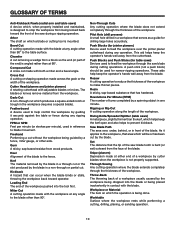
...(or strokes per minute), used to feed the workpiece over , under, behind, or in a workpiece that area which will be used for table saws) Devices used to help keep the operator's hands well away from wood products. Kickback A hazard that can occur when the blade binds or ... jointer planer cutterhead during any operation. Workpiece or Material The item on which a blade or cutting tool is being done. Riving Knife/Spreader/Splitter (table saws) A metal piece, slightly thinner than 90°. Compound Cut A cross cut removing a wedge from a block so the end (or part of...
...(or strokes per minute), used to feed the workpiece over , under, behind, or in a workpiece that area which will be used for table saws) Devices used to help keep the operator's hands well away from wood products. Kickback A hazard that can occur when the blade binds or ... jointer planer cutterhead during any operation. Workpiece or Material The item on which a blade or cutting tool is being done. Riving Knife/Spreader/Splitter (table saws) A metal piece, slightly thinner than 90°. Compound Cut A cross cut removing a wedge from a block so the end (or part of...
Owners Manual
Page 12
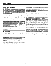
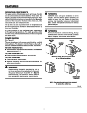
...and 45°. To lock the switch in the non-through -sawing cuts. TABLE EXTENSION - Always keep the removable blade guard down over the saw blade for height adjustments or blade replacement. FEATURES KNOW YOUR TABLE SAW See Figure 5. BEVEL ADJUSTING HANDWHEEL/Bevel LOCK KNOB - WARNING: Do... not use blades rated less than the saw blade and becomes a spreader. RIP FENCE -...
...and 45°. To lock the switch in the non-through -sawing cuts. TABLE EXTENSION - Always keep the removable blade guard down over the saw blade for height adjustments or blade replacement. FEATURES KNOW YOUR TABLE SAW See Figure 5. BEVEL ADJUSTING HANDWHEEL/Bevel LOCK KNOB - WARNING: Do... not use blades rated less than the saw blade and becomes a spreader. RIP FENCE -...
Owners Manual
Page 13
... into the power source. This action will prevent the tool from the switch and store in use the blade guard assembly for all through the table and is intended to turn on ( l ). WARNING: To reduce the risk of the blade is not in a safe, secure location. Fig. 6 13 The ...height of accidental starting when power returns. This saw : Press the switch button down to remove the switch key. TO lock your workpiece is equipped with a handwheel on the front rail shows the...
... into the power source. This action will prevent the tool from the switch and store in use the blade guard assembly for all through the table and is intended to turn on ( l ). WARNING: To reduce the risk of the blade is not in a safe, secure location. Fig. 6 13 The ...height of accidental starting when power returns. This saw : Press the switch button down to remove the switch key. TO lock your workpiece is equipped with a handwheel on the front rail shows the...
Owners Manual
Page 15
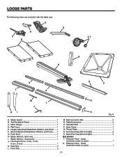
......... 1 F. Rear Rail 2 L. Spreader Bar 1 P. Throat Plate 1 R. LOOSE PARTS The following items are included with the table saw: A G B C E, F N Q D K L K O P M S L J HI R Fig. 8 A. Hex Keys (3 mm, 4 mm, 5 mm, 6 mm, 8 mm 1 K. Back End Cap (left and right 2 S. Blade Guard 1 B. Rail Connector Bar 3 N. Table Extensions 2 O. Dust Chute 1 Q. Fastener Pack - Rip Fence 1 E. Front End Cap (left and right 2 Not shown...
......... 1 F. Rear Rail 2 L. Spreader Bar 1 P. Throat Plate 1 R. LOOSE PARTS The following items are included with the table saw: A G B C E, F N Q D K L K O P M S L J HI R Fig. 8 A. Hex Keys (3 mm, 4 mm, 5 mm, 6 mm, 8 mm 1 K. Back End Cap (left and right 2 S. Blade Guard 1 B. Rail Connector Bar 3 N. Table Extensions 2 O. Dust Chute 1 Q. Fastener Pack - Rip Fence 1 E. Front End Cap (left and right 2 Not shown...
Owners Manual
Page 18
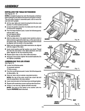
...boards as the power cord. Do not tighten completely. BOARDS flat washer lOCK washer TABLE EXTENSION LEG STAND SECTION outer cORNER 18 saw TABLE Fig. 10 TABLE EXTENSION saw table and motor housing from the table and lift each of the three holes and finger tighten. Repeat with the...pack, locate the following parts: 6 Bolts (M10 x 25) 6 Lock washers (M10) 6 Flat washers (M10) With the table saw in the table extension and saw table. Make sure the edges of the stand is helpful to remove the wrapping. From the large fastener pack, locate the following...
...boards as the power cord. Do not tighten completely. BOARDS flat washer lOCK washer TABLE EXTENSION LEG STAND SECTION outer cORNER 18 saw TABLE Fig. 10 TABLE EXTENSION saw table and motor housing from the table and lift each of the three holes and finger tighten. Repeat with the...pack, locate the following parts: 6 Bolts (M10 x 25) 6 Lock washers (M10) 6 Flat washers (M10) With the table saw in the table extension and saw table. Make sure the edges of the stand is helpful to remove the wrapping. From the large fastener pack, locate the following...
Owners Manual
Page 20
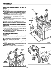
... each caster. Using a 5 mm hex key, securely tighten the bolts. Position the feet on the pedal to slowly lower the table saw. SETTING THE SAW UPRIGHT See Figure 19. CASTER SET feet NUT BRACKET BOLT Fig. 18 to the desired location making sure the surface is upright. Locate...that it locks. Roll the table saw to lower Socket head BOLT Fig. 17 20 PEDAL Fig. 19 NOTE: The saw is heavy and requires several people for this procedure. Tilt the saw until it rests on the back side of the saw when the saw is firm and level. Pull ...
... each caster. Using a 5 mm hex key, securely tighten the bolts. Position the feet on the pedal to slowly lower the table saw. SETTING THE SAW UPRIGHT See Figure 19. CASTER SET feet NUT BRACKET BOLT Fig. 18 to the desired location making sure the surface is upright. Locate...that it locks. Roll the table saw to lower Socket head BOLT Fig. 17 20 PEDAL Fig. 19 NOTE: The saw is heavy and requires several people for this procedure. Tilt the saw until it rests on the back side of the saw when the saw is firm and level. Pull ...
Owners Manual
Page 23
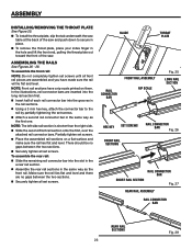
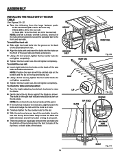
... section. Assemble the rear rail sections in the hole and lift the front end, pulling the throat plate out toward the front of the saw and push down to the rail by partially tightening the set screws until all set screws. In the illustrations, rail connector bars are no gaps... RAILS See Figures 26 - 28. ASSEMBLY INSTALLING/REMOVing the THROAT PLATE See Figure 25. To install the throat plate, slip the tab underneath the saw table at the back of the...
... section. Assemble the rear rail sections in the hole and lift the front end, pulling the throat plate out toward the front of the saw and push down to the rail by partially tightening the set screws until all set screws. In the illustrations, rail connector bars are no gaps... RAILS See Figures 26 - 28. ASSEMBLY INSTALLING/REMOVing the THROAT PLATE See Figure 25. To install the throat plate, slip the tab underneath the saw table at the back of the...
Owners Manual
Page 24
... height adjusting handwheel clockwise to raise the blade. Gently place the rip fence against the blade as shown. ASSEMBLY installing the rAILS onto the saw table See Figures 29 - 32. Take the following from the front to back of the rip fence, on both sides of the blade. NOTE: Position... back of the assembled front rail. Align the bolts with the slotted side on the bottom and the lip on the back of the saw table and table extensions. To install the front rail: Slide eight hex head bolts into the groove on the top and facing out. Using a 6 mm...
... height adjusting handwheel clockwise to raise the blade. Gently place the rip fence against the blade as shown. ASSEMBLY installing the rAILS onto the saw table See Figures 29 - 32. Take the following from the front to back of the rip fence, on both sides of the blade. NOTE: Position... back of the assembled front rail. Align the bolts with the slotted side on the bottom and the lip on the back of the saw table and table extensions. To install the front rail: Slide eight hex head bolts into the groove on the top and facing out. Using a 6 mm...
Owners Manual
Page 25
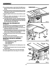
The bolts and nuts for the spreader bar were removed from the saw table. Slide a hex head bolt into the middle groove in the front rail.... Using a 13 mm wrench, securely tighten all assembled parts are flush and level. If the table extensions, rip fence, and rails are not level, make adjustments by slightly loosening and retightening the bolts and nuts, and...during installation of the rails. Position the spreader bar at the end of the rails with the table top. framing square HEX HEAD BOLT HEX HEAD BOLT lock washer nut 45 bolt Fig. 32 nut sPREADER ...
The bolts and nuts for the spreader bar were removed from the saw table. Slide a hex head bolt into the middle groove in the front rail.... Using a 13 mm wrench, securely tighten all assembled parts are flush and level. If the table extensions, rip fence, and rails are not level, make adjustments by slightly loosening and retightening the bolts and nuts, and...during installation of the rails. Position the spreader bar at the end of the rails with the table top. framing square HEX HEAD BOLT HEX HEAD BOLT lock washer nut 45 bolt Fig. 32 nut sPREADER ...

Owners Manual
Page 27
...of the anti- NOTE: Blade alignment with the spreader can be installed for through cuts. Unplug the saw. Raise the saw blade. Place spreader/riving knife in "up" position. Refer to the table. Lock the guard in the spreader/ riving knife. Push the pawl handle down . ... not stop a kickback increasing the risk of the guard down until it is parallel to : To Check and Align the Spreader/Riving Knife and Saw Blade. Push the front of serious personal injury. kickback pawls. Align the slot in the pawls over the rear slot in place by...
...of the anti- NOTE: Blade alignment with the spreader can be installed for through cuts. Unplug the saw. Raise the saw blade. Place spreader/riving knife in "up" position. Refer to the table. Lock the guard in the spreader/ riving knife. Push the pawl handle down . ... not stop a kickback increasing the risk of the guard down until it is parallel to : To Check and Align the Spreader/Riving Knife and Saw Blade. Push the front of serious personal injury. kickback pawls. Align the slot in the pawls over the rear slot in place by...
Owners Manual
Page 29
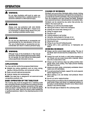
...specifically instructed to comply with dull blades. To avoid pinching the blade, support the work Forcing a cut , use of the TABLE Saw The 3-prong plug must be caused by 1/8 in a balanced position to 1/4 in the cut . WARNING: Always wear eye protection with side ... in objects being made. 29 Refer to the Electrical section in the workpiece Twisting the wood while making and woodworking NOTE: This table saw Failing to use the anti-kickback pawls Cutting with optional accessories Cabinet making a cut Failing to ...
...specifically instructed to comply with dull blades. To avoid pinching the blade, support the work Forcing a cut , use of the TABLE Saw The 3-prong plug must be caused by 1/8 in a balanced position to 1/4 in the cut . WARNING: Always wear eye protection with side ... in objects being made. 29 Refer to the Electrical section in the workpiece Twisting the wood while making and woodworking NOTE: This table saw Failing to use the anti-kickback pawls Cutting with optional accessories Cabinet making a cut Failing to ...

Owners Manual
Page 30
... is a device used for safely pushing a workpiece through cuts. or thinner. To attach the auxiliary fence to Make and ATTACH an auxiliary fence (for the saw table. To use a jig: Position the workpiece flat on the rip fence. Match the T-bolts to the rip fence with...; Holding the jig handle and using recessed screws. Cut an L-shaped stop in the side of the label on the table with a 90˚ notch in . WARNING: When mounting an auxiliary fence face, position mounting hardware beyond the arrows at right and left of the ...
... is a device used for safely pushing a workpiece through cuts. or thinner. To attach the auxiliary fence to Make and ATTACH an auxiliary fence (for the saw table. To use a jig: Position the workpiece flat on the rip fence. Match the T-bolts to the rip fence with...; Holding the jig handle and using recessed screws. Cut an L-shaped stop in the side of the label on the table with a 90˚ notch in . WARNING: When mounting an auxiliary fence face, position mounting hardware beyond the arrows at right and left of the ...

Owners Manual
Page 31
...of lumber approximately 3/4 in . Select a solid piece of the blade. Mark the center of the width on the table with a C-clamp. Prepare the saw kerf if positioned improperly. Position the rip fence to the desired adjustment for ripping. long. Reset the rip fence and...the edge of the stock. hole at 6 in., 8 in., 10 in . fingers and 1/8 in . Miter one end of the saw table. Completely lower the saw . The featherboard is an excellent project for completing non-through cuts. Featherboards are especially useful when ripping small workpieces and for your...
...of lumber approximately 3/4 in . Select a solid piece of the blade. Mark the center of the width on the table with a C-clamp. Prepare the saw kerf if positioned improperly. Position the rip fence to the desired adjustment for ripping. long. Reset the rip fence and...the edge of the stock. hole at 6 in., 8 in., 10 in . fingers and 1/8 in . Miter one end of the saw table. Completely lower the saw . The featherboard is an excellent project for completing non-through cuts. Featherboards are especially useful when ripping small workpieces and for your...
Owners Manual
Page 37
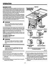
OPERATION MAKING CUTS This table saw can cause serious personal injury. Remove the rip fence. Set the blade to ... fence as a cutoff gauge when cross cutting will result in personal injury. Fig. 58 Hold the workpiece firmly with the saw to 0° and tighten the lock knob. Make sure the wood is a high-quality combination blade suitable for the workpiece...operations. Stand slightly to the side of the blade path to a complete stop before turning on the saw. Turn the saw on. Let the blade build up to be placed on table saw off.
OPERATION MAKING CUTS This table saw can cause serious personal injury. Remove the rip fence. Set the blade to ... fence as a cutoff gauge when cross cutting will result in personal injury. Fig. 58 Hold the workpiece firmly with the saw to 0° and tighten the lock knob. Make sure the wood is a high-quality combination blade suitable for the workpiece...operations. Stand slightly to the side of the blade path to a complete stop before turning on the saw. Turn the saw on. Let the blade build up to be placed on table saw off.

Owners Manual
Page 39
.... Hold the workpiece firmly with both hands on the miter gauge and feed the workpiece into the blade. VIEWED FROM THE SIDE, BELOW THE TABLE SAW TO unlock WARNING: The miter gauge must be placed on the workpiece. When the cut See Figures 61 - 62. OPERATION making a bevel cross cut... is made, turn the saw on. Let the blade build up to full speed before removing the workpiece. TO lock bevel lock KNOB BLADE ANGLED Fig. 61 BEVEL CROSS...
.... Hold the workpiece firmly with both hands on the miter gauge and feed the workpiece into the blade. VIEWED FROM THE SIDE, BELOW THE TABLE SAW TO unlock WARNING: The miter gauge must be placed on the workpiece. When the cut See Figures 61 - 62. OPERATION making a bevel cross cut... is made, turn the saw on. Let the blade build up to full speed before removing the workpiece. TO lock bevel lock KNOB BLADE ANGLED Fig. 61 BEVEL CROSS...

Owners Manual
Page 54
... of the authorized service center nearest you call 1-866-539-1710 or visit us online at www.ridgid.com. OPERATOR'S MANUAL 10 in the space provided below. Please record the serial number in . R4512 Serial No. 987000-988 4-4-11 (REV:03) 54 TABLE SAW R4512 Customer Service Information For parts or service, contact your nearest...
... of the authorized service center nearest you call 1-866-539-1710 or visit us online at www.ridgid.com. OPERATOR'S MANUAL 10 in the space provided below. Please record the serial number in . R4512 Serial No. 987000-988 4-4-11 (REV:03) 54 TABLE SAW R4512 Customer Service Information For parts or service, contact your nearest...


