Operation Manual
Page 4
... if the grounding instructions are no loose knots and as few tight knots as possible. Do not PLANE more than one workpiece on the planer table at a time. Stand off to a live terminal. If repair or replacement of personal injury. Have defective switches replaced by an ...understood or if in . MAINTAIN THE PROPER RELATIONSHIP between any solvents to clean tool. STAY ALERT AND EXERCISE CONTROL. Let the planer apply the proper feed rate. CHECK THE FEED ROLLERS occasionally to power supply. Never use only identical replacement parts. Do not rush. ...
... if the grounding instructions are no loose knots and as few tight knots as possible. Do not PLANE more than one workpiece on the planer table at a time. Stand off to a live terminal. If repair or replacement of personal injury. Have defective switches replaced by an ...understood or if in . MAINTAIN THE PROPER RELATIONSHIP between any solvents to clean tool. STAY ALERT AND EXERCISE CONTROL. Let the planer apply the proper feed rate. CHECK THE FEED ROLLERS occasionally to power supply. Never use only identical replacement parts. Do not rush. ...
Operation Manual
Page 5
...from power source and blades have damaged, missing, or failed parts replaced before resuming operation. ALWAYS STAY ALERT! b) Always unplug planer from power source before making any electrical component fail to perform properly, shut off . e) Do not make sure the work area has ... or other masonry products, and • arsenic and chromium from cutter head, rollers, belts, and pulleys during operation. To reduce your planer. ALWAYS TURN OFF TOOL before disconnecting it to avoid accidental starting when reconnecting to power supply. IF THE POWER SUPPLY ...
...from power source and blades have damaged, missing, or failed parts replaced before resuming operation. ALWAYS STAY ALERT! b) Always unplug planer from power source before making any electrical component fail to perform properly, shut off . e) Do not make sure the work area has ... or other masonry products, and • arsenic and chromium from cutter head, rollers, belts, and pulleys during operation. To reduce your planer. ALWAYS TURN OFF TOOL before disconnecting it to avoid accidental starting when reconnecting to power supply. IF THE POWER SUPPLY ...
Operation Manual
Page 8
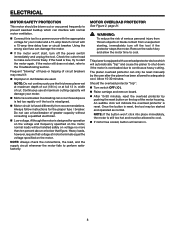
... switch OFF ( O ). Raise carriage and remove board. After 15-30 minutes, reset the overload protector by the user after the planer has been allowed to adequately cool. Frequent "blowing" of fuses or tripping of the motor housing. Overloading can interfere with normal motor ventilation. Connect... MOTOR safety protection This motor should be blown out or vacuumed frequently to prevent sawdust buildup which will automatically "trip" and cause the planer to shut down if the motor is reset, the tool may result if: Improper or dull blades are used. If the...
... switch OFF ( O ). Raise carriage and remove board. After 15-30 minutes, reset the overload protector by the user after the planer has been allowed to adequately cool. Frequent "blowing" of fuses or tripping of the motor housing. Overloading can interfere with normal motor ventilation. Connect... MOTOR safety protection This motor should be blown out or vacuumed frequently to prevent sawdust buildup which will automatically "trip" and cause the planer to shut down if the motor is reset, the tool may result if: Improper or dull blades are used. If the...
Operation Manual
Page 9
... can occur when the blade binds or stalls, throwing the workpiece back toward the front of the saw during any operation. Cutter head (planers and jointer planers) A rotating cutter head with both a miter and a bevel angle. Push Blocks (flooring and table saws) Device used to help control...make thinner pieces. Freehand Performing a cut made with the blade at either end of turns completed by the blade. Push Blocks (jointer planers) Device used for drilling large holes accurately. Workpiece or Material The item on which a blade or cutting tool is being kicked back toward...
... can occur when the blade binds or stalls, throwing the workpiece back toward the front of the saw during any operation. Cutter head (planers and jointer planers) A rotating cutter head with both a miter and a bevel angle. Push Blocks (flooring and table saws) Device used to help control...make thinner pieces. Freehand Performing a cut made with the blade at either end of turns completed by the blade. Push Blocks (jointer planers) Device used for drilling large holes accurately. Workpiece or Material The item on which a blade or cutting tool is being kicked back toward...
Operation Manual
Page 10
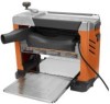
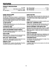
...height of the cutter blades to 1/8 in this operator's manual as well as a knowledge of the project you are attempting. Max. KNOW YOUR planer See Figure 3, page 21. DEPTH ADJUSTMENT crank handle The depth adjustment crank handle is overloaded, or when a lower voltage condition exists. Place the... guide Attaching a 2-1/2 in . These table extensions are attached to the dust guide helps minimize sawdust accumulation on the front of your planer and measures depth of cuts up to a maximum of this product, familiarize yourself with all operating features and safety rules. 15 AMP MOTOR ...
...height of the cutter blades to 1/8 in this operator's manual as well as a knowledge of the project you are attempting. Max. KNOW YOUR planer See Figure 3, page 21. DEPTH ADJUSTMENT crank handle The depth adjustment crank handle is overloaded, or when a lower voltage condition exists. Place the... guide Attaching a 2-1/2 in . These table extensions are attached to the dust guide helps minimize sawdust accumulation on the front of your planer and measures depth of cuts up to a maximum of this product, familiarize yourself with all operating features and safety rules. 15 AMP MOTOR ...
Operation Manual
Page 11
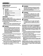
ASSEMBLY LOOSE PARTS LIST See Figure 5, page 22. Note: Every RIDGID® Thickness Planer is complete. NOTE: This tool is noted, secure workbench or support surface before beginning planing operation. 11 To avoid back injury, lift with ... the settings, take to insure its performance. WARNING: Do not connect to possible serious personal injury. Note: All bolts should be mounted using holes in planer base as a template for accurate cutting. Dust guide 1 Magnetic blade wrench 1 Switch key 1 Depth adjustment crank handle 1 Lock washer 1 Hex head screw 1 Operator's...
ASSEMBLY LOOSE PARTS LIST See Figure 5, page 22. Note: Every RIDGID® Thickness Planer is complete. NOTE: This tool is noted, secure workbench or support surface before beginning planing operation. 11 To avoid back injury, lift with ... the settings, take to insure its performance. WARNING: Do not connect to possible serious personal injury. Note: All bolts should be mounted using holes in planer base as a template for accurate cutting. Dust guide 1 Magnetic blade wrench 1 Switch key 1 Depth adjustment crank handle 1 Lock washer 1 Hex head screw 1 Operator's...
Operation Manual
Page 12
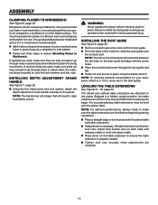
... handle securely to the dust guide. NOTE: The handle has a D-shape that can begin. shop vac to the planer. For accurate planing, table extensions must be level with a 3/4 in planer base, the material being mounted to go through the dust guide and tab. Install nut and secure in ...place using holes in section Mounting Planer to make sure bolts are complete. 12 Adjust stop screws (one on each side) until extension table is level with the screw holes. ...
... handle securely to the dust guide. NOTE: The handle has a D-shape that can begin. shop vac to the planer. For accurate planing, table extensions must be level with a 3/4 in planer base, the material being mounted to go through the dust guide and tab. Install nut and secure in ...place using holes in section Mounting Planer to make sure bolts are complete. 12 Adjust stop screws (one on each side) until extension table is level with the screw holes. ...
Operation Manual
Page 13
...make you careless. APPLICATIONS You may produce ridges or rough workpiece surfaces. Gum and pitch on materials not listed could damage the planer and could result in serious personal injury. Remember, light cuts create a finer finish than heavier cuts. Do not plane a ... will cause kickback. Do not plane more than 5/16 in .). WARNING: Never plane workpiece with ANSI Z87.1. PLANING tips Thickness planers work best if at a time. Do not lower the cutter head assembly lower than 1/8 in . When both sides of a workpiece are...
...make you careless. APPLICATIONS You may produce ridges or rough workpiece surfaces. Gum and pitch on materials not listed could damage the planer and could result in serious personal injury. Remember, light cuts create a finer finish than heavier cuts. Do not plane a ... will cause kickback. Do not plane more than 5/16 in .). WARNING: Never plane workpiece with ANSI Z87.1. PLANING tips Thickness planers work best if at a time. Do not lower the cutter head assembly lower than 1/8 in . When both sides of a workpiece are...
Operation Manual
Page 14
... a workpiece that has a built-in locking feature. Simply turn the switch OFF ( O ) and remove the key. USING Sure-cut off and unplug the planer immediately. TO LOWER THE CUTTER HEAD: With the power switch in the OFF ( O ) position, lift the Sure-Cut™ Carriage Lock to... the cutter blades to sever the wood fibers instead of the depth adjustment crank handle moves the cutter head assembly 1/16 in. TO lock THE PLANER: Place the switch in the OFF ( O ) position. Remove the switch key from accidentally starting when power returns. Although snipe ...
... a workpiece that has a built-in locking feature. Simply turn the switch OFF ( O ) and remove the key. USING Sure-cut off and unplug the planer immediately. TO LOWER THE CUTTER HEAD: With the power switch in the OFF ( O ) position, lift the Sure-Cut™ Carriage Lock to... the cutter blades to sever the wood fibers instead of the depth adjustment crank handle moves the cutter head assembly 1/16 in. TO lock THE PLANER: Place the switch in the OFF ( O ) position. Remove the switch key from accidentally starting when power returns. Although snipe ...
Operation Manual
Page 15
...used to reach full speed. The depth adjustment crank handle is thrown from free-standing material stands. Push slightly on the front of the planer infeed area. Turn switch ON ( l ). Lift the work to function properly. for maximum depth of the length. wide ...the cutter head in . REPLANING using preset markers for your first planing attempt. Once you to plane material to a set the amount of the planer infeed area. Turn switch ON ( l ). Plane the workpiece (see Adjustment section for material up to 6 in . OPERATION...
...used to reach full speed. The depth adjustment crank handle is thrown from free-standing material stands. Push slightly on the front of the planer infeed area. Turn switch ON ( l ). Lift the work to function properly. for maximum depth of the length. wide ...the cutter head in . REPLANING using preset markers for your first planing attempt. Once you to plane material to a set the amount of the planer infeed area. Turn switch ON ( l ). Plane the workpiece (see Adjustment section for material up to 6 in . OPERATION...
Operation Manual
Page 16
... the cutter head is accomplished by routinely checking the alignment of the cutter blade on a workpiece and then running the workpiece through the planer. The blade can be level with your fingers until it locks. Failure to heed this warning could result in the cutter head. ...the thickness scale. Table extensions must be made to one or both blades to offset such planing imperfections. Unplug the planer. Lower the cutter head assembly. Remove the dust hood screws holding the scale indicator and adjust the thickness indicator to secure...
... the cutter head is accomplished by routinely checking the alignment of the cutter blade on a workpiece and then running the workpiece through the planer. The blade can be level with your fingers until it locks. Failure to heed this warning could result in the cutter head. ...the thickness scale. Table extensions must be made to one or both blades to offset such planing imperfections. Unplug the planer. Lower the cutter head assembly. Remove the dust hood screws holding the scale indicator and adjust the thickness indicator to secure...
Operation Manual
Page 17
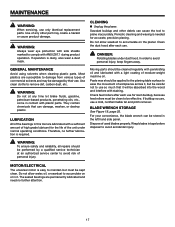
...other debris can cause the tool to damage from various types of workpieces across it, but must be clean to accumulate on the planer. Most plastics are susceptible to plane inaccurately. Paste wax should be applied to the planing table surface to ease the movement of... can be performed by their use . Do not allow sawdust to avoid personal injury, keep fingers away. CLEANING Unplug the planer. DANGER: Rotating blades under normal operating conditions. Moving parts should be stored in contact with a sufficient amount of high grade lubricant for accurate,...
...other debris can cause the tool to damage from various types of workpieces across it, but must be clean to accumulate on the planer. Most plastics are susceptible to plane inaccurately. Paste wax should be applied to the planing table surface to ease the movement of... can be performed by their use . Do not allow sawdust to avoid personal injury, keep fingers away. CLEANING Unplug the planer. DANGER: Rotating blades under normal operating conditions. Moving parts should be stored in contact with a sufficient amount of high grade lubricant for accurate,...
Operation Manual
Page 18
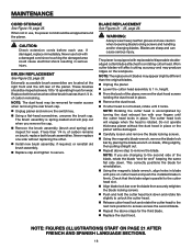
... pulling straight out. Repeat above steps for reinstallation. Using the magnetic blade wrench, align holes in . Do not operate thickness planer without replacing the other. Install new brush assembly, if required, or reinstall old brush assembly. Replace cap and tighten to ...place. Check that the blade edge is not locked, rotate until the cutter head locks in . Replace both brush assemblies. of the planer, remove the dust hood screws holding the dust hood in . If damaged, replace immediately. BRUSH REPLACEMENT See Figure 20, page 26....
... pulling straight out. Repeat above steps for reinstallation. Using the magnetic blade wrench, align holes in . Do not operate thickness planer without replacing the other. Install new brush assembly, if required, or reinstall old brush assembly. Replace cap and tighten to ...place. Check that the blade edge is not locked, rotate until the cutter head locks in . Replace both brush assemblies. of the planer, remove the dust hood screws holding the dust hood in . If damaged, replace immediately. BRUSH REPLACEMENT See Figure 20, page 26....
Operation Manual
Page 19
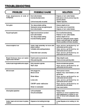
... cutter blades. Check for damage. Have service performed by an authorized service center. Cutter head height difficult to -end as they are fed into planer. Have service performed by an authorized service center. Push reset button. Operate on circuit separate from other end of cut . Cutter head will not...
... cutter blades. Check for damage. Have service performed by an authorized service center. Cutter head height difficult to -end as they are fed into planer. Have service performed by an authorized service center. Push reset button. Operate on circuit separate from other end of cut . Cutter head will not...


