

Operation Manual
Page 2
... Assembly...12-21 Operation...22-28 Adjustments...29-30 Maintenance...31-32 Warranty...33 Parts Ordering and Service...Back page INTRODUCTION This product has many features for making it easy to maintain and operate. 2 - Safety, performance, and dependability have been ...
... Assembly...12-21 Operation...22-28 Adjustments...29-30 Maintenance...31-32 Warranty...33 Parts Ordering and Service...Back page INTRODUCTION This product has many features for making it easy to maintain and operate. 2 - Safety, performance, and dependability have been ...
Operation Manual
Page 3
... DISCONNECT TOOLS. TURN THE POWER OFF. Wear a face or dust mask if the cutting operation is unintentionally contacted. CHECK DAMAGED PARTS. Wear hearing protection during extended periods of personal injury. USE THE RIGHT DIRECTION OF FEED. Keep cord away from work when...are removed from receptacle. Rubber gloves and nonskid footwear (rubber soled boots) are not safety glasses. SECURE WORK. Form habit of parts, mounting and any tool. USE RECOMMENDED ACCESSORIES. Never yank cord to contain long hair. ALWAYS WEAR SAFETY GLASSES WITH...
... DISCONNECT TOOLS. TURN THE POWER OFF. Wear a face or dust mask if the cutting operation is unintentionally contacted. CHECK DAMAGED PARTS. Wear hearing protection during extended periods of personal injury. USE THE RIGHT DIRECTION OF FEED. Keep cord away from work when...are removed from receptacle. Rubber gloves and nonskid footwear (rubber soled boots) are not safety glasses. SECURE WORK. Form habit of parts, mounting and any tool. USE RECOMMENDED ACCESSORIES. Never yank cord to contain long hair. ALWAYS WEAR SAFETY GLASSES WITH...
Operation Manual
Page 4
... NOT operate A tool while under the influence of personal injury. Do not use of accessories are secure. Never touch WHEEL or other parts may cause the risk of drugs, alcohol, or any medication. When servicing use washers or arbor nuts that are defective or incorrect. ...with insulation having an outer surface that accept the tool's plug. DO NOT MODIFY the plug provided. Never use only identical replacement parts. If repair or replacement of cord location and keep it will not fit the outlet, have repaired by a qualified service technician at an...
... NOT operate A tool while under the influence of personal injury. Do not use of accessories are secure. Never touch WHEEL or other parts may cause the risk of drugs, alcohol, or any medication. When servicing use washers or arbor nuts that are defective or incorrect. ...with insulation having an outer surface that accept the tool's plug. DO NOT MODIFY the plug provided. Never use only identical replacement parts. If repair or replacement of cord location and keep it will not fit the outlet, have repaired by a qualified service technician at an...
Operation Manual
Page 5
... a well ventilated area, and work with approved safety equipment, such as those dust masks that no obstructions will interfere with safe operation BEFORE performing any part of your body in line with smooth edge cutting wheels free of these chemicals are specially designed to filter out microscopic particles. 5 - Refer to them...
... a well ventilated area, and work with approved safety equipment, such as those dust masks that no obstructions will interfere with safe operation BEFORE performing any part of your body in line with smooth edge cutting wheels free of these chemicals are specially designed to filter out microscopic particles. 5 - Refer to them...
Operation Manual
Page 8
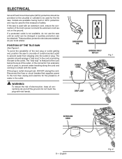
... be provided on the ground. If the plug or outlet does get wet, DO NOT unplug the cord. Disconnect the fuse or circuit breaker that part of the cord below the level of water in GFCI protection and may be obtained. The "drip loop" is not available, do not use the...
... be provided on the ground. If the plug or outlet does get wet, DO NOT unplug the cord. Disconnect the fuse or circuit breaker that part of the cord below the level of water in GFCI protection and may be obtained. The "drip loop" is not available, do not use the...

Operation Manual
Page 11
... washer (small 2 OO- Handle (short 1 SS - English Tile cutting wheel 1 C - Motor head assembly 1 D - Hex nut 2 J - Lower brace 1 S - Lock nut (small 8 Y - Never Dry Valve 1 UU - LOOSE PARTS The following items are included with cleaning nozzle 1 P - Water tray frame assembly 1 B - Cap bolt (short 2 E - Long clear tube 1 F - Inner leg assembly 1 G - Sleeve 4 I GG l H J m FF RR...
... washer (small 2 OO- Handle (short 1 SS - English Tile cutting wheel 1 C - Motor head assembly 1 D - Hex nut 2 J - Lower brace 1 S - Lock nut (small 8 Y - Never Dry Valve 1 UU - LOOSE PARTS The following items are included with cleaning nozzle 1 P - Water tray frame assembly 1 B - Cap bolt (short 2 E - Long clear tube 1 F - Inner leg assembly 1 G - Sleeve 4 I GG l H J m FF RR...
Operation Manual
Page 12
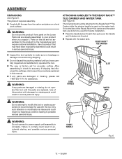
... the packing material until assembly is used for handle installation. Place the handle below the slot then pull up on the Loose Parts List are already assembled to your product when you have been improperly assembled could result in serious personal injury. ASSEMBLY UNPACKING See Figure 5....WATER TANK See Figure 6. The long handle should be used on a level work surface. WARNING: Do not use with damaged or missing parts could result in serious personal injury. long handle slot water tank warning: Do not attempt to modify this product with this product if any...
... the packing material until assembly is used for handle installation. Place the handle below the slot then pull up on the Loose Parts List are already assembled to your product when you have been improperly assembled could result in serious personal injury. ASSEMBLY UNPACKING See Figure 5....WATER TANK See Figure 6. The long handle should be used on a level work surface. WARNING: Do not use with damaged or missing parts could result in serious personal injury. long handle slot water tank warning: Do not attempt to modify this product with this product if any...
Operation Manual
Page 13
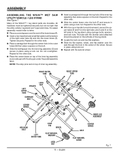
... two flat washers. Slide the flat washer, wheel, and flat washer onto the axle through the top hole of the WSUV™ / leg stand parts are movable. Do not overtighten. Tighten securely. The tube with the second wheel. ASSEMBLY ASSEMBLING THE WSUV™ Wet Saw Utility Vehicle / leg stand See...
... two flat washers. Slide the flat washer, wheel, and flat washer onto the axle through the top hole of the WSUV™ / leg stand parts are movable. Do not overtighten. Tighten securely. The tube with the second wheel. ASSEMBLY ASSEMBLING THE WSUV™ Wet Saw Utility Vehicle / leg stand See...
Operation Manual
Page 26
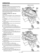
... be cut on position. Let the cutting wheel build up to full speed and wait for the wheel to get wet before removing any part of the material. 26 - OPERATION MAKING CUTS Always draw the line to be cut on material. Set the miter guide to 0°, tighten the... the cutting wheel. When the cut is clear of the material. Wait for the cutting wheel to come to a complete stop before removing any part of the cutting wheel before turning on the saw OFF. Wait for the cutting wheel to come to a complete stop before moving the material into...
... be cut on position. Let the cutting wheel build up to full speed and wait for the wheel to get wet before removing any part of the material. 26 - OPERATION MAKING CUTS Always draw the line to be cut on material. Set the miter guide to 0°, tighten the... the cutting wheel. When the cut is clear of the material. Wait for the cutting wheel to come to a complete stop before removing any part of the cutting wheel before turning on the saw OFF. Wait for the cutting wheel to come to a complete stop before moving the material into...
Operation Manual
Page 27
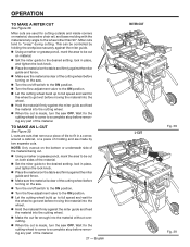
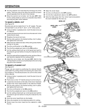
... on the table and firmly against the miter guide and fence. Make sure the material is clear of the cutting wheel before removing any part of the material. NOTE: Only overcut on the bottom or underneath side of the material being cut. Using a marker or grease pencil, mark the... area to the on material, decorative chair rail, and base molding with the material at any part of the material. 27 - To make a miter cut See Figure 38. English MITER cut l-cut on both sides of the cutting wheel before turning on...
... on the table and firmly against the miter guide and fence. Make sure the material is clear of the cutting wheel before removing any part of the material. NOTE: Only overcut on the bottom or underneath side of the material being cut. Using a marker or grease pencil, mark the... area to the on material, decorative chair rail, and base molding with the material at any part of the material. 27 - To make a miter cut See Figure 38. English MITER cut l-cut on both sides of the cutting wheel before turning on...
Operation Manual
Page 28
... of the motor head and position the motor head upward to its maximum height. Set the miter guide to a complete stop before removing any part of the material. Beveled cuts can be cut . 28 - This allows pieces to be cut from 0° to full speed and wait for the next... made by the handle. Move the material into the desired position for the cutting wheel to come to a complete stop before removing any part of the material. Raise the motor head. Turn the on/off switch to the on position. Turn the flow adjustment valve to...
... of the motor head and position the motor head upward to its maximum height. Set the miter guide to a complete stop before removing any part of the material. Beveled cuts can be cut . 28 - This allows pieces to be cut from 0° to full speed and wait for the next... made by the handle. Move the material into the desired position for the cutting wheel to come to a complete stop before removing any part of the material. Raise the motor head. Turn the on/off switch to the on position. Turn the flow adjustment valve to...

Operation Manual
Page 29
...: Before performing any screws for this warning could result in the left and right rails. Place a framing square against the fence and the flat part of the wheel. Using set screws to adjust, move both rails at the factory for each adjustment. Adjusting lower TABLE ROLLERS Cam bolt nut...
...: Before performing any screws for this warning could result in the left and right rails. Place a framing square against the fence and the flat part of the wheel. Using set screws to adjust, move both rails at the factory for each adjustment. Adjusting lower TABLE ROLLERS Cam bolt nut...

Operation Manual
Page 31
...Brush assembly is oriented correctly (straight) and replace. 31 - Do not replace one side without replacing the other parts may result in contact with light oil (e.g., WD40). Brush Brush cap assembly WARNING: Always wear eye protection with ANSI...Z87.1 during product operation. WARNING: Do not at any other . Reassemble using solvents when cleaning plastic parts. Brush REPLACEMENT See Figure 46. Replace both brushes when either has less than 1/4 in brush tube. ...length of motor and that should be damaged by their use only identical RIDGID replacement parts.
...Brush assembly is oriented correctly (straight) and replace. 31 - Do not replace one side without replacing the other parts may result in contact with light oil (e.g., WD40). Brush Brush cap assembly WARNING: Always wear eye protection with ANSI...Z87.1 during product operation. WARNING: Do not at any other . Reassemble using solvents when cleaning plastic parts. Brush REPLACEMENT See Figure 46. Replace both brushes when either has less than 1/4 in brush tube. ...length of motor and that should be damaged by their use only identical RIDGID replacement parts.

Operation Manual
Page 33
... gives you specific legal rights, and you must present proof of purchase and return all original equipment packaged with the performance of this RIDGID® tool for any part covered under the warranty, at our option, at no charge to One World Technologies, Inc., attn...: RIDGID® Hand Held and Stationary Power Tool Technical Service at www.ridgid.com. One World Technologies, Inc. WARRANTY RIDGID® HAND HELD AND STATIONARY POWER TOOL 3 YEAR LIMITED SERVICE WARRANTY...
... gives you specific legal rights, and you must present proof of purchase and return all original equipment packaged with the performance of this RIDGID® tool for any part covered under the warranty, at our option, at no charge to One World Technologies, Inc., attn...: RIDGID® Hand Held and Stationary Power Tool Technical Service at www.ridgid.com. One World Technologies, Inc. WARRANTY RIDGID® HAND HELD AND STATIONARY POWER TOOL 3 YEAR LIMITED SERVICE WARRANTY...

Repair Sheet
Page 3
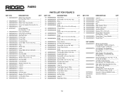
...1 Etiqueta de advertencia de tope de la mesa de puente 1 Sujetador de boquilla rociado 1 Tornillo (M4 x 8 mm, cab. R4090 KEY P/N 1 080009008701 2 080009008002 3 080009008003 4 080009008004 5 080009008005 6 080009008006 7 080009008007 8 080009008008 9 080009008009 10 080009008010 11 080009008011 ... Water Tray Cap Band 1 Screw ( M4 x 10 mm 1 Hex Key (2.5 mm 1 Hex Key (6 mm 1 Hex Key (8 mm 1 PARTS LIST FOR FIGURE A PIÈCE RÉF. 1 080009008701 2 080009008002 3 080009008003 4 080009008004 5 080009008005 6 080009008006 7 080009008007 8 080009008008 9 080009008009 10...
...1 Etiqueta de advertencia de tope de la mesa de puente 1 Sujetador de boquilla rociado 1 Tornillo (M4 x 8 mm, cab. R4090 KEY P/N 1 080009008701 2 080009008002 3 080009008003 4 080009008004 5 080009008005 6 080009008006 7 080009008007 8 080009008008 9 080009008009 10 080009008010 11 080009008011 ... Water Tray Cap Band 1 Screw ( M4 x 10 mm 1 Hex Key (2.5 mm 1 Hex Key (6 mm 1 Hex Key (8 mm 1 PARTS LIST FOR FIGURE A PIÈCE RÉF. 1 080009008701 2 080009008002 3 080009008003 4 080009008004 5 080009008005 6 080009008006 7 080009008007 8 080009008008 9 080009008009 10...

Repair Sheet
Page 5
... 52 080009008078 53 080009008073 54 080009008076 Middle Table 1 Sliding Tube Sleeve 4 Rod 2 Rear Table 1 Miter Guide Assembly (Inc. Hd 1 Water Flow Valve Assembly (Inc. Hd 5 5 R4090 PARTS LIST FOR FIGURE B KEY P/N DESCRIPTION QTY KEY P/N DESCRIPTION QTY KEY P/N DESCRIPTION QTY 1 080009008025 Screw (M5 x 10 mm, Soc. Hd 1 Miter Guide 1 Miter Guide Holder 1 Sliding...
... 52 080009008078 53 080009008073 54 080009008076 Middle Table 1 Sliding Tube Sleeve 4 Rod 2 Rear Table 1 Miter Guide Assembly (Inc. Hd 1 Water Flow Valve Assembly (Inc. Hd 5 5 R4090 PARTS LIST FOR FIGURE B KEY P/N DESCRIPTION QTY KEY P/N DESCRIPTION QTY KEY P/N DESCRIPTION QTY 1 080009008025 Screw (M5 x 10 mm, Soc. Hd 1 Miter Guide 1 Miter Guide Holder 1 Sliding...

Repair Sheet
Page 9
... (M5 x 35 mm, Rd. Key Nos. 76-77, and 132 1 Depth Stop Adjust Label 1 Bushing 2 Lock Washer (M4 2 Knob 1 Lock Pin 1 O-Ring (D10.6 x D6.8 x 1.9t 1 9 R4090 PARTS LIST FOR FIGURE C KEY P/N DESCRIPTION QTY KEY P/N DESCRIPTION QTY KEY P/N DESCRIPTION QTY 1 080009008095 Screw (M8, Special 2 2 080009008094 Lower Slider 1 3 080009008093 Rear Wear Plate 1 4 080009008089 Bevel...
... (M5 x 35 mm, Rd. Key Nos. 76-77, and 132 1 Depth Stop Adjust Label 1 Bushing 2 Lock Washer (M4 2 Knob 1 Lock Pin 1 O-Ring (D10.6 x D6.8 x 1.9t 1 9 R4090 PARTS LIST FOR FIGURE C KEY P/N DESCRIPTION QTY KEY P/N DESCRIPTION QTY KEY P/N DESCRIPTION QTY 1 080009008095 Screw (M8, Special 2 2 080009008094 Lower Slider 1 3 080009008093 Rear Wear Plate 1 4 080009008089 Bevel...

Repair Sheet
Page 10
... Spindle 1 Wheel Nut (Spindle) (5/8 in.-18 1 Outer Washer 1 Splash Guard 1 Wheel Guard Lock 1 Tile Cutting Wheel (10 in 1 Inner Washer 1 E-Ring (E-3 2 Screw (M5 x 6 mm, Rd. R4090 PARTS LIST FOR FIGURE C KEY P/N DESCRIPTION QTY KEY P/N DESCRIPTION QTY KEY P/N DESCRIPTION QTY 82 080009008132 83 080009008131 84 080009008713 85 080009008114 86 080009008115 87 080009008117 88...
... Spindle 1 Wheel Nut (Spindle) (5/8 in.-18 1 Outer Washer 1 Splash Guard 1 Wheel Guard Lock 1 Tile Cutting Wheel (10 in 1 Inner Washer 1 E-Ring (E-3 2 Screw (M5 x 6 mm, Rd. R4090 PARTS LIST FOR FIGURE C KEY P/N DESCRIPTION QTY KEY P/N DESCRIPTION QTY KEY P/N DESCRIPTION QTY 82 080009008132 83 080009008131 84 080009008713 85 080009008114 86 080009008115 87 080009008117 88...
Repair Sheet
Page 16
...Label F 2 Label G 2 Unlock Label 1 Washer (D13 x D28 x 2t 2 Left Support Tube 1 Wheel (8 in . OD x 1/4 in 2 PARTS LIST FOR FIGURE D KEY P/N 33 080009008283 34 080009008284 35 080009008302 36 080009008919 37 080009008233 38 080009008229 39 080009008236 40 080009008228 41 080009008237 42 080009008234 43...Nos. 49, 61, 62 and 63 1 Water Hose Kit (Inc. Key Nos. 37-43, 46-47 and 56-60; R4090 KEY P/N DESCRIPTION QTY 1 080009008707 2 080009008221 3 080009008222 4 080009008712 5 080009008216 6 987321001 7 080009005918 8 080009004912 9 080009005920 10 ...
...Label F 2 Label G 2 Unlock Label 1 Washer (D13 x D28 x 2t 2 Left Support Tube 1 Wheel (8 in . OD x 1/4 in 2 PARTS LIST FOR FIGURE D KEY P/N 33 080009008283 34 080009008284 35 080009008302 36 080009008919 37 080009008233 38 080009008229 39 080009008236 40 080009008228 41 080009008237 42 080009008234 43...Nos. 49, 61, 62 and 63 1 Water Hose Kit (Inc. Key Nos. 37-43, 46-47 and 56-60; R4090 KEY P/N DESCRIPTION QTY 1 080009008707 2 080009008221 3 080009008222 4 080009008712 5 080009008216 6 987321001 7 080009005918 8 080009004912 9 080009005920 10 ...


