

Operation Manual
Page 2
......2 General Safety Rules...3-4 Specific Safety Rules...5 Symbols...6 Electrical...7-8 Features...9-10 Tools Needed...10 Loose Parts...11 Assembly...12-21 Operation...22-28 Adjustments...29-30 Maintenance...31-32 Warranty...33 Parts Ordering and Service...Back page INTRODUCTION This product has many features for making it easy to maintain and operate. 2 - Safety, performance, and...
......2 General Safety Rules...3-4 Specific Safety Rules...5 Symbols...6 Electrical...7-8 Features...9-10 Tools Needed...10 Loose Parts...11 Assembly...12-21 Operation...22-28 Adjustments...29-30 Maintenance...31-32 Warranty...33 Parts Ordering and Service...Back page INTRODUCTION This product has many features for making it easy to maintain and operate. 2 - Safety, performance, and...
Operation Manual
Page 3
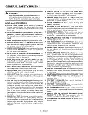
... accessories. Consult the operator's manual for better and safer performance. GENERAL SAFETY RULES WARNING: Read and understand all instructions listed below, may result in electric shock, fire and/or serious personal injury. Make sure your hand and frees both hands to a complete stop. PROTECT YOUR LUNGS. A wire gauge size (A.W.G.) of at least 14 is in loss of parts, mounting and any tool. USE RECOMMENDED ACCESSORIES. Be sure switch...
... accessories. Consult the operator's manual for better and safer performance. GENERAL SAFETY RULES WARNING: Read and understand all instructions listed below, may result in electric shock, fire and/or serious personal injury. Make sure your hand and frees both hands to a complete stop. PROTECT YOUR LUNGS. A wire gauge size (A.W.G.) of at least 14 is in loss of parts, mounting and any tool. USE RECOMMENDED ACCESSORIES. Be sure switch...
Operation Manual
Page 4
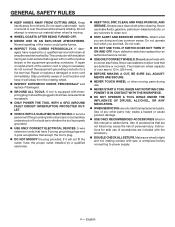
... to power supply. 4 - Keep hands away from oil and grease. Do not use washers or arbor nuts that accept the tool's plug. DO NOT MODIFY the plug provided. Instructions for safe use a clean cloth when cleaning. GENERAL SAFETY RULES KEEP HANDS AWAY FROM CUTTING AREA. Do not attempt to clean tool. STAY ALERT AND EXERCISE CONTROL. If repair or replacement of the electric cord or...
... to power supply. 4 - Keep hands away from oil and grease. Do not use washers or arbor nuts that accept the tool's plug. DO NOT MODIFY the plug provided. Instructions for safe use a clean cloth when cleaning. GENERAL SAFETY RULES KEEP HANDS AWAY FROM CUTTING AREA. Do not attempt to clean tool. STAY ALERT AND EXERCISE CONTROL. If repair or replacement of the electric cord or...
Operation Manual
Page 5
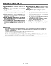
... the path of the wheel. NEVER attempt to free a stalled wheel without first turning the saw OFF and disconnecting the saw from chemically-treated lumber. Some examples of work. SPECIFIC SAFETY RULES SECURE work firmly against the miter guide or fence. NEVER stand or have the following markings: a) Wear eye, hearing, and breathing protection. d) Use tool only with smooth edge cutting wheels free of openings, grooves...
... the path of the wheel. NEVER attempt to free a stalled wheel without first turning the saw OFF and disconnecting the saw from chemically-treated lumber. Some examples of work. SPECIFIC SAFETY RULES SECURE work firmly against the miter guide or fence. NEVER stand or have the following markings: a) Wear eye, hearing, and breathing protection. d) Use tool only with smooth edge cutting wheels free of openings, grooves...

Operation Manual
Page 7
... equipped with all local codes and ordinances. Repair or replace a damaged or worn cord immediately. Only round jacketed cords listed by the letters "W-A" or "W" on any cord to reduce the risk of the working with a qualified electrician or service personnel if the grounding instructions are intended for lights cannot properly carry a power tool motor. Do not use . Do not abuse extension cords and do not yank...
... equipped with all local codes and ordinances. Repair or replace a damaged or worn cord immediately. Only round jacketed cords listed by the letters "W-A" or "W" on any cord to reduce the risk of the working with a qualified electrician or service personnel if the grounding instructions are intended for lights cannot properly carry a power tool motor. Do not use . Do not abuse extension cords and do not yank...
Operation Manual
Page 10
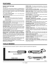
.... The sliding table allows the user to the cutting wheel. VARIABLE SPEED DIAL - Turn the diverter valve to the right and use of water to slide the workpiece into the water tank. MITER GUIDE - Adjusts the flow of this tool. FEATURES KNOW YOUR tILE saw . CLEANING NOZZLE - MULTI-POSITION CUTTING HEAD - SUBMERSIBLE PUMP - When cutting larger tile, the extensions keeps work area for assembly and alignment: phillips screwdriver FRAMING SQUARE 10 - Provides...
.... The sliding table allows the user to the cutting wheel. VARIABLE SPEED DIAL - Turn the diverter valve to the right and use of water to slide the workpiece into the water tank. MITER GUIDE - Adjusts the flow of this tool. FEATURES KNOW YOUR tILE saw . CLEANING NOZZLE - MULTI-POSITION CUTTING HEAD - SUBMERSIBLE PUMP - When cutting larger tile, the extensions keeps work area for assembly and alignment: phillips screwdriver FRAMING SQUARE 10 - Provides...

Operation Manual
Page 11
... valve and mounting bracket 1 FF - Spacer (curved 2 MM- Flat washer (medium 2 PP - Hose clamps (metal 2 11 - Inner leg assembly 1 G - Miter guide 1 N - Left upper tube 1 R - Hose clamps (plastic 2 JJ - Handle (long 1 TT - Motor head assembly 1 D - Right upper tube 1 Q - Left outer tube 1 V - Water tray 1 HH - Screws 2 KK - Water filter 1 NN- English Lock nut 4 L - Center brace 1 DD - Wheel 2 O - Ready Rack™ Tile Carrier 1 U - Flat washer (large 2 QQ- Water pump 1 GG - Wheel wrench 1 BB - Sliding table...
... valve and mounting bracket 1 FF - Spacer (curved 2 MM- Flat washer (medium 2 PP - Hose clamps (metal 2 11 - Inner leg assembly 1 G - Miter guide 1 N - Left upper tube 1 R - Hose clamps (plastic 2 JJ - Handle (long 1 TT - Motor head assembly 1 D - Right upper tube 1 Q - Left outer tube 1 V - Water tray 1 HH - Screws 2 KK - Water filter 1 NN- English Lock nut 4 L - Center brace 1 DD - Wheel 2 O - Ready Rack™ Tile Carrier 1 U - Flat washer (large 2 QQ- Water pump 1 GG - Wheel wrench 1 BB - Sliding table...

Operation Manual
Page 14
... using lock nuts. Finger tighten using nuts. Slide long cap bolts into the rail locking the table. English Cap bolt (short) Water tray Sleeve frame Cap bolt (long) Fig. 9 Push the pin into sleeve. Installing motor head ASSEMBLY to unlock Stand Fig. 8 Hex Motor nut head assembly 14 - Installing the water tray frame assembly to the leg stand See Figure 8. Lock the table stop by-pass by -pass SLIDING TABLE LOCK LEVER Lock nut Short carriage bolt table lock...
... using lock nuts. Finger tighten using nuts. Slide long cap bolts into the rail locking the table. English Cap bolt (short) Water tray Sleeve frame Cap bolt (long) Fig. 9 Push the pin into sleeve. Installing motor head ASSEMBLY to unlock Stand Fig. 8 Hex Motor nut head assembly 14 - Installing the water tray frame assembly to the leg stand See Figure 8. Lock the table stop by-pass by -pass SLIDING TABLE LOCK LEVER Lock nut Short carriage bolt table lock...

Operation Manual
Page 17
... brace until it locks into an outlet or extension cord. installING NEVER DRY VALVE, water pump, and water tank See Figure 17. Unscrew the connector from both the left or right. Tighten the knob securely before turning on the leg stand. English check valve Fig. 17 ASSEMBLY Installing the miter guide See Figure 16. The miter guide can be used from the never...
... brace until it locks into an outlet or extension cord. installING NEVER DRY VALVE, water pump, and water tank See Figure 17. Unscrew the connector from both the left or right. Tighten the knob securely before turning on the leg stand. English check valve Fig. 17 ASSEMBLY Installing the miter guide See Figure 16. The miter guide can be used from the never...

Operation Manual
Page 20
... load speed of the saw . Turn the wheel guard lock counterclockwise to unlock. Pull the wheel guard open to expose the spindle. Depress and hold the spindle lock. Using the wheel wrench provided, remove the wheel nut. Failure to heed this tool. tile cutting wheel is the maximum wheel capacity of this warning could result in personal injury. Never use the 10 in . Spindle Spindle lock Wheel guard lock To loosen Wheel wrench Fig. 23 Inner washer Wheel nut Outer washer...
... load speed of the saw . Turn the wheel guard lock counterclockwise to unlock. Pull the wheel guard open to expose the spindle. Depress and hold the spindle lock. Using the wheel wrench provided, remove the wheel nut. Failure to heed this tool. tile cutting wheel is the maximum wheel capacity of this warning could result in personal injury. Never use the 10 in . Spindle Spindle lock Wheel guard lock To loosen Wheel wrench Fig. 23 Inner washer Wheel nut Outer washer...

Operation Manual
Page 21
... adjustments by turning the lock knob to rain or other than those specified herein may result in the cutting position using the laser adjustment dials. Align the laser line and the mark with the wheel in hazardous radiation exposure. Release the spindle lock button. Close and lock the wheel guard. Avoid direct eye contact with the flats on the spindle. When the laser guide switch is against the cutting wheel. Place wheel nut on spindle...
... adjustments by turning the lock knob to rain or other than those specified herein may result in the cutting position using the laser adjustment dials. Align the laser line and the mark with the wheel in hazardous radiation exposure. Release the spindle lock button. Close and lock the wheel guard. Avoid direct eye contact with the flats on the spindle. When the laser guide switch is against the cutting wheel. Place wheel nut on spindle...

Operation Manual
Page 22
... listed below: Straight line cutting operations such as cross cutting, mitering, ripping, and beveling NOTE: This saw arm is always running. English Pump switch always on with On/Off Switch WARNING: Always wear eye protection with side shields marked to comply with tools to make you careless. Pump switch on Pump switch always off . APPLICATIONS You may use fresh water by connecting a garden hose...
... listed below: Straight line cutting operations such as cross cutting, mitering, ripping, and beveling NOTE: This saw arm is always running. English Pump switch always on with On/Off Switch WARNING: Always wear eye protection with side shields marked to comply with tools to make you careless. Pump switch on Pump switch always off . APPLICATIONS You may use fresh water by connecting a garden hose...

Operation Manual
Page 23
... supply valve. Slowly turn on , water will prevent the tool from the water main. Turn the diverter valve to the left to run water through the hole in locking feature. To use , turn the switch OFF. On/Off Switch Switch off SWITCH See Figure 28. Watch water flow over the cutting wheel when the saw on the lower brace of accidental starting when power returns...
... supply valve. Slowly turn on , water will prevent the tool from the water main. Turn the diverter valve to the left to run water through the hole in locking feature. To use , turn the switch OFF. On/Off Switch Switch off SWITCH See Figure 28. Watch water flow over the cutting wheel when the saw on the lower brace of accidental starting when power returns...

Operation Manual
Page 24
... fence then make the cut in the most stable position on the saw arm See Figure 30. NOTE: the table stop the middle table from moving the cutting head to the desired position on the "D" handle and pull out the lock pin. Firmly grasp the "D" handle and apply downward pressure while at the same time turning the lock knob clockwise to lock. Push in the lock pin...
... fence then make the cut in the most stable position on the saw arm See Figure 30. NOTE: the table stop the middle table from moving the cutting head to the desired position on the "D" handle and pull out the lock pin. Firmly grasp the "D" handle and apply downward pressure while at the same time turning the lock knob clockwise to lock. Push in the lock pin...

Operation Manual
Page 25
...;. DEPTH STOP wing nut unlock bevel lock lever grip bevel indicator screw D-handle Fig. 33 lock D-handle bevel scale Fig. 34 screw 25 - OPERATION TO CHANGE cutting wheel DEPTH See Figure 33. Retighten screw. With the wheel at 90°, the bevel indicator should be pointing to 0°. Loosen the screw and position the bevel indicator to point to 45°. Set the wheel to the desired angle. Tighten bevel control by lifting the bevel lock lever. ...
...;. DEPTH STOP wing nut unlock bevel lock lever grip bevel indicator screw D-handle Fig. 33 lock D-handle bevel scale Fig. 34 screw 25 - OPERATION TO CHANGE cutting wheel DEPTH See Figure 33. Retighten screw. With the wheel at 90°, the bevel indicator should be pointing to 0°. Loosen the screw and position the bevel indicator to point to 45°. Set the wheel to the desired angle. Tighten bevel control by lifting the bevel lock lever. ...
Operation Manual
Page 26
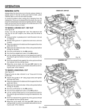
... cuts". Adjust miter guide to 45° using a marker or grease pencil. A common problem when cutting tile is back on position. Turn the flow adjustment valve to get wet before removing any part of the material. 26 - Wait for the wheel to the on position. Let the cutting wheel build up and recut the tile slicing off switch to the on track. OPERATION MAKING CUTS...
... cuts". Adjust miter guide to 45° using a marker or grease pencil. A common problem when cutting tile is back on position. Turn the flow adjustment valve to get wet before removing any part of the material. 26 - Wait for the wheel to the on position. Let the cutting wheel build up and recut the tile slicing off switch to the on track. OPERATION MAKING CUTS...
Operation Manual
Page 28
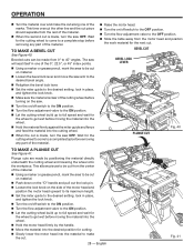
...; Set the miter guide to the desired setting, lock in place, and tighten the lock knob. Make sure the material is clear of the cutting wheel before turning on the saw. Turn the on/off switch to the OFF position. Turn the flow adjustment valve to 45° angles. Wait for the cutting wheel to come to a complete stop before removing any part of the material. Raise the motor head. Turn...
...; Set the miter guide to the desired setting, lock in place, and tighten the lock knob. Make sure the material is clear of the cutting wheel before turning on the saw. Turn the on/off switch to the OFF position. Turn the flow adjustment valve to 45° angles. Wait for the cutting wheel to come to a complete stop before removing any part of the material. Raise the motor head. Turn...

Operation Manual
Page 29
Set screw Framing square Hex bolts To square the cutting wheel to wear. Adjusting UPPER TABLE ROLLER set screws to side, or is visibly off track adjustments may be sure adjustments are needed . Once the rollers are touching the rail, tighten the cam bolt nut securely. If the table doesn't slide smoothly, seems too loose on the left side of time, readjustment will probably become necessary due...
Set screw Framing square Hex bolts To square the cutting wheel to wear. Adjusting UPPER TABLE ROLLER set screws to side, or is visibly off track adjustments may be sure adjustments are needed . Once the rollers are touching the rail, tighten the cam bolt nut securely. If the table doesn't slide smoothly, seems too loose on the left side of time, readjustment will probably become necessary due...

Operation Manual
Page 30
... screw. ADJUSTMENTS POSITIVE STOP ADJUSTMENTS See Figure 44. If the cutting wheel is not perfectly vertical (0°): Loosen the bevel lock knob. Place a combination square beside the wheel. Using a wrench, turn the 45° hex bolt until the wheel is square to the table and the hex bolt is not an exact 45°: Set the saw arm to place the laser guide line and wheel on the saw...
... screw. ADJUSTMENTS POSITIVE STOP ADJUSTMENTS See Figure 44. If the cutting wheel is not perfectly vertical (0°): Loosen the bevel lock knob. Place a combination square beside the wheel. Using a wrench, turn the 45° hex bolt until the wheel is square to the table and the hex bolt is not an exact 45°: Set the saw arm to place the laser guide line and wheel on the saw...

Operation Manual
Page 31
... motor and that should be damaged by their use. The saw . Remove brush cap with a screwdriver. Do not replace one side without replacing the other parts may create a hazard or cause product damage. MAINTENANCE WARNING: When servicing, use , clean the rails so the table will pop out when you remove brush cap. Remove brush assembly. Check for wear. GENERAL MAINTENANCE Avoid using new brush assemblies. After extended use only identical RIDGID replacement parts...
... motor and that should be damaged by their use. The saw . Remove brush cap with a screwdriver. Do not replace one side without replacing the other parts may create a hazard or cause product damage. MAINTENANCE WARNING: When servicing, use , clean the rails so the table will pop out when you remove brush cap. Remove brush assembly. Check for wear. GENERAL MAINTENANCE Avoid using new brush assemblies. After extended use only identical RIDGID replacement parts...


